
A feedforward air-conditioning energy management method for high-speed railway sleeper compartment

Abstract
In this paper, we propose a feedforward air conditioning temperature control method for high-speed railway locomotives with sleeper compartments to improve energy efficiency. First, we construct the geometric model of two typical types of compartments and three types of passengers. Then, based on the analysis of possible passenger layout patterns in each compartment, we utilize computational fluid dynamics simulations to calculate the optimal air volume for each pattern. The optimal air volume is calculated to guarantee the passenger comfort level and reduce the energy cost. In addition, we adopt an image recognition method to detect the number and types of passengers in each compartment. Passenger layout patterns serve as independent variables to determine the corresponding optimal air volume. Finally, numerical simulations were conducted to verify the effectiveness of the proposed method.
Keywords
1. INTRODUCTION
The high-speed rail system is a fundamental part of China’s rail transit[1,2]. As a high-end field of national industrial manufacturing, its development has strategic significance for China to seize future technological command[3]. The application of artificial intelligence technology in a high-speed railway locomotive is helpful for providing convenient, comfortable, and environmentally friendly travel. Currently, the energy-saving efficiency improvement of high-speed railways mainly relies on the optimization of locomotive design, lightweight body design, and energy management of internal systems. Among them, it is challenging to seek breakthroughs upon the shape and body design of the high-speed railway since they have already been comprehensively developed in the last decades. Compared with reducing air resistance, the cost of energy-saving by improving the energy management level of the air conditioning system is much lower. Currently, the high-speed railway air conditioning system accounts for about 40% of the actual power of energy-consuming components. However, there is still no appropriate energy management method for cooling or heating energy consumption. Static experimental results of high-speed railway air conditioning systems show that the oscillation of temperature is significant[4,5], which will cause the increase of the intermittent power for balancing the heat exhaled by passengers. Besides, this oscillation will also directly affect passengers’ comfort.
A relevant test-bed has been built to detect air temperature, humidity, wind speed, ambient air pressure, renewal speed, and other parameters in the train. However, this work has focused on data acquisition and analysis and does not provide practical methods to adjust the air volume/temperature to improve the passengers’ comfort. At present, the temperature control in the compartment depends on the manual operation of stewards. Stewards manually open or close the air outlet damper by operating the control panel. Once this control action is set, the fan speed and the air volume are fixed. If the setting is not appropriate, it may cause insufficient air supply and may affect the passengers’ comfort level. If the temperature is set too high, it may cause excessive air supply or the frequent start and stop of the compressor, resulting in unnecessary energy consumption. In addition, it will take a long time for the temperature to be controlled by adjusting the air volume. Moreover, due to the disability of non-polar speed regulation, the actual air volume supplied in the compartment does not match the required quantity. When leaving the compartment, the cooling or heating process will continue, leading to a waste of energy[6].
Thus, we aim to design an air conditioning control system that will help improve energy-saving efficiency and comfort level. This objective can be achieved by applying a feedforward loop to the original controller. The motivation of this work is shown in Figure 1. It has been shown that different distribution patterns of passengers in a compartment will significantly affect the temperature. An image-based passenger detection method is used to find the pattern in a compartment. Then, based on the CFD analysis, the optimal air volume can be found.

Figure 1. Motivations and contributions of locomotive air conditioner energy management method.
The main contributions of the paper are as follows:
A novel feedforward air conditioning energy management method is established for locomotive sleeper compartments to improve energy efficiency. The YOLOv3 method is utilized for passenger recognition in locomotive corridors, which helps to recognize the distribution pattern in the compartments.
The computational fluid dynamics (CFD) method is utilized to calculate the optimal air volume for several scenarios of different types of passengers in two kinds of compartments. Numerical examples demonstrated the effectiveness of the proposed method.
The remainder of the paper is organized as follows. In Section 2, we firstly design the physical models of a locomotive compartment and the passengers in three kinds of body shapes. For two typical compartments, passenger models are distributed to imitate all possible real conditions, especially for those with more than one person. Then, we utilize finite element analysis software to mesh the surfaces of the models above and design a solver to simulate and pick up the optimized consequences for each condition[7,8], based on governing equations of fluid flow and heat transfer[9]. In Section 3, we adopt YOLOv3 to recognize the number of passengers in/out of each room in real-time, which has more advantages in the exact practical scene than other methods. Section 4 concludes this paper with some promising directions.
2. OPTIMAL AIR VOLUME ANALYSIS FOR LOCOMOTIVE SLEEPER COMPARTMENT
The feedforward mechanism, as shown in Figure 2, provides an initial air volume through actuators, which matches the number, distribution, or type of passengers in a compartment. When the reference temperature signal is set, the actuators, including the refrigeration compressor and ventilating fan, influence the flow field and the temperature of each compartment. The actual temperature is measured by the sensors installed and is sent back to the comparator to calculate the differences[4,5]. This section aims to find the relationship between the optimal air volume supply and the number of passengers in a compartment by simulation. All possible conditions are considered, which means that, as long as the passenger situation is given, the corresponding optimal air volume can be determined. Therefore, as illustrated in Section 3, we applied image recognition technology (YOLOv3) to get the passenger situation timely.

Figure 2. Feedforward and feedback control flow chart of locomotive air conditioner system.
To simulate the air conditioning system of rail transit locomotives with sleepers by CFD[8,9], it is necessary to establish the physical models of sleeper compartments based on four-person compartments and single compartments. Then, the physical model of humans should be established according to the common size of the human body structure, which would be used to calculate the heat loss. After meshing the surface of the models in finite element simulation software, series of simulations and boundary conditions are set. After the calculation of the models with different numbers and distribution of passengers lying on sleeper conditions, the considered results are selected by the principals followed[10]. The wind speed around the body surface is between 0.06 and 0.1 m/s, which is to meet the requirements of breeze speed; the temperature around the body surface should be between 23 °C and 25 °C. After interpolating the simulation results in this interval, the minimum air volume of the fitting function is taken as the optimal air volume in that condition. As for the same number of passengers with a different distribution, each group of calculation results is averaged to facilitate the control of the air volume supplied.
2.1. Geometric model construction
Due to the substantial uncertainty of the arrangement and combination of the upper bed passengers and the relatively wide compartment space, the contribution of human body shape on the ambient temperature field of the four-person compartments is negligible. Therefore, the standard model of human body surface area is adopted when analyzing this kind of compartment. The model of the full four-person sleeper is shown in Figure 3.
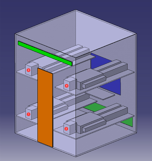
Figure 3. Geometric model of the four-person compartment with passengers.
In the figure, the blue area is the window, the orange area is the door, and the green areas are air inlet and outlet, respectively. A valve is installed on the inlet. The serial number of beds is marked on the head of lying passengers, which indicates the specific position of each bed. The distribution mode of passengers can be described by these numbers.
The compartment model is[10] 2.0 m long, 2.0 m wide, and 2.53 m high. The window is 1.0 m wide and 0.8 m high, and the door is 0.5 m wide and 1.9 m high. The lower berth in the compartment is 0.43 m high, 1.96 m long, and 0.76 m wide from the ground, and the upper berth is 1.56 m high from the ground, 1.85 m long, and 0.7 m wide. A passenger lies on the berth, with head near the door and feet 0.05 m from the wall with the window. The table near the window is 0.75 m high from the ground, 0.4 m long, and 0.625 m wide. The size of the air supply outlet is 1.8 m × 0.25 m and 0.1 m above the ground. The air outlet above the compartment door is 1.8 m × 0.l m and 2.3 m above the ground. Considering the influence of the heat exhaled by the human body, the parameters of body size are as follows: height is 1.7 m, chest depth is 0.2 m, and shoulder breadth is 0.44 m.
There are 15 distribution modes according to the number and conditions of the passengers, but 12 of them are symmetrical to each other, which means only 9 kinds of distribution modes should be calculated, as shown in Figure 4. In Figure 4a–i, the number of passengers increases from one to four. The structure inside of the compartment is symmetrical with respect to the plane where the door and window located. When there is only one passenger in the compartment (Figure 4a, b), it is explicit that lying on Bed1 has the same effect as on Bed 2, and lying on Bed 3 has the same effect as on Bed 4. Therefore, these two shown conditions should be taken into consideration. When there are two passengers in the compartment (Figure 4c–f), lying on Beds 1 and 3 has the same effect as on Beds 2 and 4, and lying on Beds 2 and 3 has the same effect as on Beds 1 and 4. When there are three passengers in the compartment (Figure 4g, h), the absence of Bed 1 has the same effect as of Bed 2, and the absence of Bed 3 has the same effect as of Bed 4. Figure 4i shows the condition with four passengers.
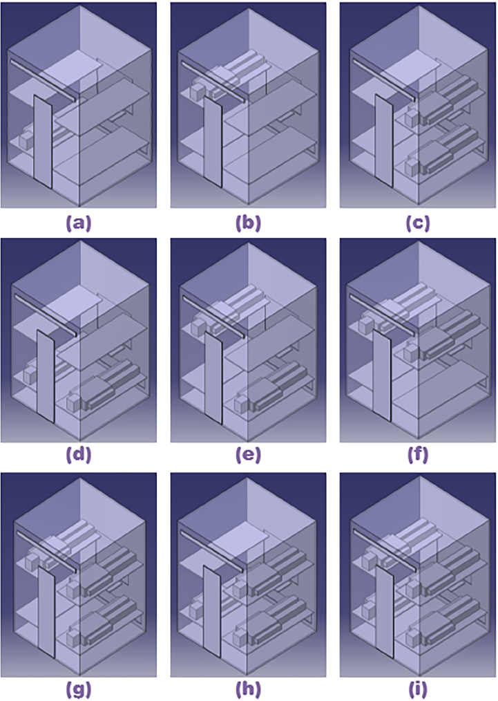
Figure 4. Possible passenger distribution in the four-person compartment.
The model of a single capsule compartment is simplified as a quarter of the four-person one. In this condition, the shape of the human body plays a significant part due to the heat exhaled from a distinct area of the skin surface. Thus, we also take the body’s shape into consideration and divide the passengers into three types: thin, standard, and strong. The resulting lying scenes of passengers in this kind of compartment are shown in Figure 5.

Figure 5. Geometric model of single-person compartment with three types of passengers.
2.2. Governing equations of fluid flow and heat transfer
The CFD method is utilized to analyze the fluid flow in the sleeper compartments of rail transit. Therefore, this subsection briefly introduces the theoretical basis of the method. The basic governing equation is the mathematical equation of the conservation law of physics when fluid moves. The commonly used governing equations have the following expressions (in the inertial rectangular coordinate system)[11,12].
2.2.1. Mass conservation equation
Any flow problem must satisfy the law of conservation of mass. The law can be expressed as follows: the increase of the mass of a fluid micro-element in a unit time is equal to the net mass flowing into the microelement at the same time, according to which the mass conservation equation can be expressed as:
where ρ is the air density and u, v, and w are the velocity components in x, y, and z coordinate directions, respectively.
2.2.2. Momentum conservation equation
Conservation of momentum is the manifestation of Newton’s second law in fluid flow. The law can be expressed as follows: the changing ratio of the momentum of a fluid micro-element with respect to time is equal to the sum of all external forces acting on the micro-element, according to which the momentum conservation equation can be expressed as:
where p is the pressure; μ is the aerodynamic viscosity; Fx, Fy, and Fz are the components of volume force along the three coordinate directions of x, y, and z, respectively; and v is the velocity vector.
2.2.3. Energy conservation equation
Conservation of energy is one of the basic laws that must be satisfied in the flow systems in which heat exchange occurs. The law can be expressed as follows: the increase rate of thermodynamic energy in the micro-element is equal to the net heat flux entering the micro-element plus the work done on it by the volume force and surface force, according to witch the energy conservation equation can be expressed as:
where Cp is the specific heat capacity of the fluid, T is the temperature, k is the heat transfer coefficient of the fluid, and ST is the viscous dissipation term, which is the superposition of the internal heat source of the fluid and the heat energy converted from mechanical energy transfer due to the viscous effect.
For a compressible fluid, the density ρ will change in the movement; besides, ρ is a thermodynamic variable. Therefore, a constitutive equation should be introduced, i.e. a state equation, which characterizes the internal relationship among the thermodynamic variables of the fluid so that the equations are closed. For an ideal gas, the equation of state can be expressed as follows:
where R is the molar gas constant and T is the temperature of gas.
2.3. Numerical calculation method of turbulent flow
The airflow in the sleeper compartments of rail transit discussed in this paper is turbulent flow. The basic mechanism of turbulent flow is not fully understood yet, owing to its extreme complexity. Its main characteristics can be summarized as diffusion, randomness, vorticity, and dissipation. Thus, there are three methods to deal with the problems on turbulence flow at present: direct numerical simulation (DNS), large eddy simulation (LES), and Reynolds average Navier-Stokes (RANS). DNS uses the N – S equation to calculate different parameters in fluid flow directly. LES applies the N – S equation to the motion of large-scale eddy. They both mean that high computing power is needed when the situation is complicated. RNS regards transient parameters as the sum of time mean and pulsation, including the Reynolds stress equation method and turbulent viscosity coefficient method, which can be afforded by current computing conditions by the latter method. The standard k –ε model and RNG k –ε model are mainly used in solving RANS[13].
The essence of numerical calculation is first to solve the series of partial differential equations of fluid flow and heat transfer which are discretized at each node according to certain mathematical or physical laws. Then, the equations can be solved by introducing boundary conditions. That is to say, a discrete variable field replaces the analytic solutions of primitive differential equations. There are various ways to solve such equations: finite difference method (FDM), finite element method (FEM), finite analysis method (FAM), boundary element method (BEM), finite volume method (FVM), etc. The first four methods have better versatility and are commonly used in the engineering field, and numerous fluid flow calculation software packages adopt FVM as the core method: STAR-CD, FLUENT, FLOW3D, CFX, PHOENICS, etc.
FVM evolves from FDM and has some of the advantages of FEM, while it is based on the conservation equation of integral form rather than differential form, of which each control volume is defined by the computational grid. FVM focuses on the construction of discrete equations from the physical point of view, and each coefficient has a clear physical meaning. Therefore, this paper also utilizes FVM as the theoretical basis to study the flow field in the sleeper compartments under the action of a high-speed rail train air conditioning system[14].
2.4. Boundary conditions and assumptions
The calculation in this paper is based on a common operating condition in summer. The outdoor ambient temperature is 35 °C and the relative humidity is 60%. The inlet boundary conditions are as follows: the air supply temperature is 21 °C, the air supply outlet is set at the side near the window, k is the turbulent kinetic energy, and ε is the turbulent energy dissipation rate. The outlet boundary conditions are as follows: inlet pressure of the outlet is simplified as ambient. The wall boundary conditions are as follows: the wall surfaces at both ends and the door side are taken as the heat insulation surface, while the roof, floor, and window surfaces are taken as the third boundary condition.
According to TB1951-87, the design parameters of passenger train air conditioning, the comprehensive heat transfer coefficient K of the train is taken as 1.16 w/m K. The heat load in the box, i.e., the heat dissipation of human body, is calculated as 116.3 W for standard passenger type. Thus, the heat exhaled by thin and strong types are calculated according to their relative proportion of skin area.
In the simulation process, the following assumptions need to be set:
When constructing the model, the heat transfer between each compartment and between corridors and the compartment are ignored. Only the internal elements of the compartment model are considered.
The airtightness of the model is ideal, and there is no direct gas exchange with the outside world except for the air inlet with a valve and the outlet.
No heat transfer through the walls or windows of the model is considered.
The weather factors are considered as external temperature compositely and act upon the window glass.
2.5. Meshing and numerical calculation of the cases
According to the governing equations of fluid flow and heat transfer, we built a solver in numerical simulation software with the geometric model above. It must be clarified that, to save the modeling time cost due to the continuously changing valve size, we simplified the process of adjusting the area of the outlet with a constant airspeed into adjusting the airspeed with a fixed outlet. The simplification is practical because the target characteristic we need is the optimal volume, which is the product of the airspeed and the area of the outlet.
Because the model is generally complex, it is meshed, as shown in Figure 6. In addition, the total number of elements is up to 1,310,434.
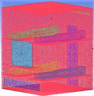
Figure 6. Meshing the surface of compartment model and passenger model.
The optimal air volume can be calculated, as shown in Tables 1 and 2. Since cameras that recognize passengers are installed in the corridor, it is unrealistic to know about the specific distribution of passengers in a compartment. It is also necessary to protect passengers’ privacy. These are the reasons that we average the consequence of each scene with the same number of passengers to get the eventual optimal volume.
The optimal air volume related to the type of passengers for single-person compartment
| No. | Type | Optimal air Speed (m/s) | Area of outlet (m2) | Optimal air volume (m3/h) |
|---|---|---|---|---|
| 1 | Thin | 0.76 | 0.0144 | |
| 2 | Standard | 0.8 | 0.019 | 0.0152 |
| 3 | Strong | 0.9 | 0.0171 |
The optimal air volume related to the number and distribution of passengers for four-person compartment
| No. | Number of passengers | Position | Optimal air speed (m/s) | Area of outlet (m2) | Optimal air volume (m3/h) | Volume Averaged by number of passengers (m3/h) |
|---|---|---|---|---|---|---|
| 1 | 1 | 0.26 | 0.117 | |||
| 2 | 1 | 2 | 0.26 | 0.117 | 0.117 | |
| 3 | 3 | 0.26 | 0.117 | |||
| 4 | 4 | 0.26 | 0.117 | |||
| 5 | 12 | 0.3 | 0.135 | |||
| 6 | 34 | 0.26 | 0.117 | |||
| 7 | 2 | 13 | 0.26 | 0.117 | 0.1215 | |
| 8 | 24 | 0.26 | 0.45 | 0.117 | ||
| 9 | 14 | 0.27 | 0.1215 | |||
| 10 | 23 | 0.27 | 0.1215 | |||
| 11 | 123 | 0.3 | 0.135 | |||
| 12 | 3 | 124 | 0.3 | 0.135 | 0.135 | |
| 13 | 134 | 0.3 | 0.135 | |||
| 14 | 234 | 0.3 | 0.135 | |||
| 15 | 4 | 1234 | 0.3 | 0.135 | 0.135 |
From the results above, the following conclusions can be drawn:
According to the data in
Table 1 , the optimal air volume is closely related to the passengers’ type in the single compartment. The passengers’ types represent the different surface areas of the human body, which influence the heat exhaled by the passenger into the compartment, according to which there is a margin for energy conservation.According to the data in
Table 2 , the optimal air output is closely related to the number of people in the four-person compartment. As passengers leave the compartment, the number of people decreases with the optimal air volume, which can provide a margin for energy conservation.According to
Tables 1 and2 , the specific relationship between the optimal air volume and the number or type of passengers is clear.
Then, we can obtain the energy saving efficiency as the ratio of consequences calculated above and the originally supplied air volume. The latter equals the largest volume a compartment obtains, as shown in Table 3.
Energy saving efficiency analysis
| Type of compartment | Number of passengers | Type of passenger | Optimal volume (m3/h) | Energy saving efficiency (%) |
|---|---|---|---|---|
| 1 | 0.117 | 13.3 | ||
| 4 | 2 | - | 0.1215 | 10.1 |
| 3 4 | 0.135 | 0 | ||
| thin | 0.0144 | 12.73 | ||
| 1 | - | standard | 0.0152 | 7.88 |
| strong | 0.0171 | -3.64 |
3. PASSENGER DETECTION AND EXPERIMENT
To get the number of passengers in the compartment in real time and save the manufacturing cost on the application of the design system on a locomotive with sleepers, we adopt the image recognition technology on the monitors installed on the end of the locomotive corridor. When the monitor captures scenes in real time within a continuous frame, the images are conveyed to a processor to detect the number of passengers walking in or out of a compartment in a carriage.
3.1. Passenger detection by YOLOv3
In this paper, we adopt YOLOv3 as the passenger detection and enumerating method. Compared with YOLOv1, YOLOv2, and other network structures, the YOLOv3 network pays more attention to features[15]. An up sample and fusion method similar to FPN is used to detect on multiple scale feature maps, which can significantly improve the detection effect of small targets[16]. Since we utilize a camera installed on the end of a carriage corridor for monitoring the image, the passengers near the other end are small. Thus, YOLOv3 is a helpful tool to improve the correct rate of passenger detection in this exact scenario[17,18]. In this process, first, the features are extracted from the input image through the feature extraction network to obtain a feature map of a certain size; for example, if it is 13×13, then the input image would be divided into 13×13 grid cells. After that, if the central coordinate in the ground truth falls in a grid cell, the cell predicts the object. The structure of the YOLOv3 network we adopt is shown in Figure 7. CBL means ”convolution + batch Normalization + leaky relu”; Res means ResBlock,which is the basic module of RESNET (residual network); FPN means ”feature pyramid networks”; and Conv means ”convolution”.

Figure 7. Structure of YOLOv3 network adopted.
Res with a number indicates how many ResUnit are in this ResBlock. This part is a large component of YOLOv3. It partially learns from the residual structure of RESNET, which can deepen the network structure. During iterative CBL (convolution + batch Normalization + leaky relu) and up sample steps, the up samples of the middle layer of Darknet and a layer behind it are spliced. The operation of splicing is different from that of the residual add-in layer. Splicing expands the tensor dimension, while add is only direct addition and cannot change the dimension. There are three scales of output, namely 13×13, 26×26, and 52×52, which are odd numbers so that the grid has a central position. There is a connection between each scale. For example, the scale 13×13 output is used to detect large targets, 26×26 medium ones, and 52×52 small ones. Utilizing the network, it outputs the bounding box of passengers walking in or out of each compartment and then enumerates the number in time to detect the real scenario in each room.
3.2. Detection experiment in actual scenario
To verify the feasibility of passenger detection, we utilized a camera with a similar resolution to the one on the locomotive. The test environment is vital because the shooting direction is perpendicular to the access channel of compartments to imitate the real locomotive corridor. The test consequence is shown in Figure 8, in which we can see that the detection effectiveness is considerable. The number in the lower right corner of the picture indicates the chronological order of the screenshots. However, several frames’ bounding boxes are missing during the recognition progress because the pictures’ angle is extraordinary compared with those in the training set. Thus, in future work, we plan to add the corresponding images taken, label them ourselves, and train the detection model to improve the detection accuracy.
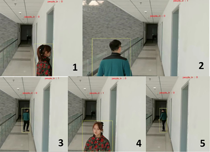
Figure 8. Test consequence of passenger detection.
3.3. Passenger surface temperature under the energy management method
To verify the effectiveness of the energy management method, the passenger’s surface temperature contour plot for a regular passenger in a single-person compartment is given in Figure 9. It can be seen that the surface temperature satisfies the design requirement, which demonstrates the optimal volume for this case that meets passenger comfort level and reduces energy cost.
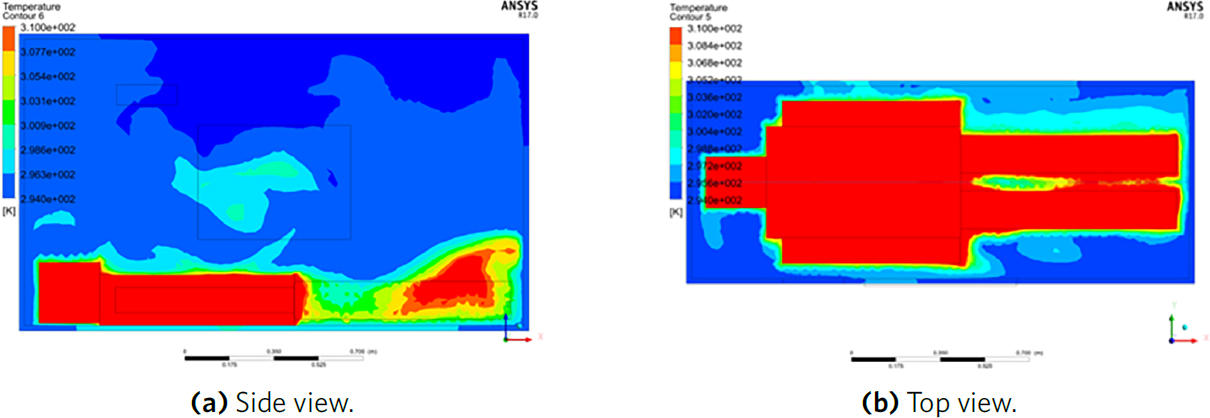
Figure 9. Regular passenger’s temperature contour plot in a single-person compartment.
4. CONCLUSION
In this paper, we design a feedforward temperature control system for a high-speed railway air conditioner. We construct the geometric models of two typical types of compartments in locomotives. Then, we adopt numerical simulation methods to calculate the optimal air volume for each passenger distribution or body type scene. By supplying the optimal air volume into the room, the efficiency of energy-saving is considerable. Compared with the original air conditioning system, the optimal volume control method avoids waste of energy when the compressor of the old system should be switched on and off frequently and provides a reference to the temperature field as a feedforward loop to comfort passengers. Then, we utilize the YOLOv3 network as the passenger detection method, which provides good test effectiveness in the actual scenario. We tested the detection efficiency in a similar scene. Compared with the original temperature adjusting process, we provide an optimal signal to the valve and ventilating fan and input the optimal air volume to reduce the negative impact of changing heat exhaled by passengers in and out in real time.
DECLARATIONS
Authors’ contributions
Conceptualization, Methodology, CFD modelling, Writing-Original draft: Li Z, Deng J
Method Validation, Writing - review and editing: Chen J
Availability of data and materials
Not applicable.
Financial support and sponsorship
None.
Conflicts of interest
All authors declared that there are no conflicts of interest.
Ethical approval and consent to participate
Not applicable
Consent for publication
The individuals in Figure 8 have consented to the publication.
Copyright
The Author(s) 2021.
REFERENCES
1. Lin S, Dhakal PR, Wu Z. The impact of high-speed railway on china’s regional economic growth based on the perspective of regional heterogeneity of quality of place. Sustainability 2021;13.
2. Momenitabar M, Ebrahimi ZD, Arani M. A systematic and analytical review of the socioeconomic and environmental impact of the deployed high-speed rail (HSR) systems on the world. arXiv preprint arXiv:200304452 :2020.
3. Wang H. Into the Fast Lane: High-speed rail to put 2022 Winter Olympics preparations and regionaldevelopment on a smart track. Beijing Review 2020:20-1. Available from: http://www.bjreview.com/Photo_Gallery/Into_the_Fast_Lane/202001/t20200107_800189326.html.
4. Winther MP, Anthony W. Air conditioning system for railway cars. US: 1940.
5. Li W, Tong H, Hou C. Research on air-conditioning system of railway traffic trainset at home and abroad. Jiangxi Building Materials 2019.
6. Liu ZQ. Research on test method for energy consumption of air-conditioning units on railway vehicles. Rolling Stock 2019;57:5-8.
7. Yousaf R, Fiala D, Wagner A. Numerical simulation of human radiation heat transfer using a mathematical model of human physiology and computational fluid dynamics (CFD). In: High Performance Computing in Science and Engineering ‘07. Springer Berlin Heidelberg; 2008. pp. 647-66.
8. Stamou AI, Katsiris I, Politis M, Schaelin A. Applying a CFD model to evaluate thermal comfort in the MPC amphitheatre of The Olympic Games “Athens 2004”. Engineering Applications of Computational Fluid Mechanics 2008;2:41-50.
9. Sorensen DN, Voigt LK. Modelling flow and heat transfer around a seated human body by computational fluid dynamics. Building & Environment 2003;38:753-62.
10. Yang RH, Zou SH, C ZD. Numerical simulation of heat exchange and ventilation environment in soft sleeper box of air-conditioned train. Journal of Hunan University of Science & Technology Natural Science Edition 2012:121-5.
11. Patera AT. A spectral element method for fluid dynamics: Laminar flow in a channel expansion. Journal of Computational Physics 1984;54:468-88.
12. Rana P, Bhargava R. Flow and heat transfer of a nanofluid over a nonlinearly stretching sheet: a numerical study. Communications in Nonlinear Science and Numerical Simulation 2012;17:212-26.
13. Murakami S, Kato S, Jie Z. Flow and temperature fields around human body with various room air distribution, CFD study on computational thermal mannequin part 1. Ashrae Transactions 1997;103:3-15.
14. Prek M. Thermodynamic analysis of human heat and mass transfer and their impact on thermal comfort. International Journal of Heat and Mass Transfer 2005;48:731-39.
15. Redmon J, Farhadi A. YOLOv3: An Incremental Improvement. arXiv e-prints 2018:1804.02767.
16. Maher M. A robust multiclass 3D object recognition based on modern YOLO deep learning algorithms. Concurrency Computat Pract Exper 2021:34.
Cite This Article
Export citation file: BibTeX | RIS
OAE Style
Li Z, Chen J, Deng J. A feedforward air-conditioning energy management method for high-speed railway sleeper compartment. Complex Eng Syst 2021;1:10. http://dx.doi.org/10.20517/ces.2021.14
AMA Style
Li Z, Chen J, Deng J. A feedforward air-conditioning energy management method for high-speed railway sleeper compartment. Complex Engineering Systems. 2021; 1(2): 10. http://dx.doi.org/10.20517/ces.2021.14
Chicago/Turabian Style
Li, Zhuoyun, Jicheng Chen, Jinghuai Deng. 2021. "A feedforward air-conditioning energy management method for high-speed railway sleeper compartment" Complex Engineering Systems. 1, no.2: 10. http://dx.doi.org/10.20517/ces.2021.14
ACS Style
Li, Z.; Chen J.; Deng J. A feedforward air-conditioning energy management method for high-speed railway sleeper compartment. Complex. Eng. Syst. 2021, 1, 10. http://dx.doi.org/10.20517/ces.2021.14
About This Article
Copyright

Data & Comments
Data


 Cite This Article 13 clicks

 Like This Article 31
likes
Like This Article 31
likes


Comments
Comments must be written in English. Spam, offensive content, impersonation, and private information will not be permitted. If any comment is reported and identified as inappropriate content by OAE staff, the comment will be removed without notice. If you have any queries or need any help, please contact us at support@oaepublish.com.