
Developing and testing a remotely operated vehicle with a seven-function manipulator
 0
0
Abstract
This paper presents the development and testing of a remotely operated vehicle (ROV). The outstanding ability of this ROV lies in its underwater hovering positioning control. At the same time, it is equipped with a seven-function underwater electric operation manipulator and the master-slave control mode is adopted. These are obvious advantages over other medium-sized ROVs. The control hardware architecture and control software architecture of this ROV are also provided. Finally, the test results of the depth trajectory tracking control, heading trajectory tracking control and hover control in the lake environment are presented and analyzed.
Keywords
1. INTRODUCTION
Remotely operated vehicles (ROVs) are playing an important role in underwater detection, marine resources development and other fields[1-3]. According to the weight or size, ROVs can be divided into four categories: (1) observation-class ROVs; (2) light-sized ROVs; (3) medium-sized ROVs; and (4) heavy-sized ROVs[4-7].
Generally speaking, observation-class ROVs can only carry cameras for observation within a short range of 100 meters. Its weight ranges from a few kilograms to over ten kilograms. In addition to carrying cameras, light-sized ROVs can generally be equipped with single beam forward-looking sonar or multi-beam forward-looking sonars. The main task with these ROVs is underwater observation. However, they have larger weight and stronger flow resistance. The operational depth can generally reach 300 m. The weight of medium-sized ROVs is typically over 300 kg, with the maximum operation depth up to 1000 m. Medium-sized ROVs can be equipped with manipulators for underwater operations. The weight of heavy-sized ROVs can reach several tons to dozens of tons, which are mainly for complex deep-sea operation tasks.
At present, due to the complexity of underwater operation tasks, it is difficult for observation-class ROVs and light-sized ROVs to meet the requirements of operation tasks due to a lack of operation equipment. Heavy-sized ROVs are too expensive and difficult to operate, and thus unsuitable for a wide range of applications. Relatively speaking, hundreds of kilograms of medium-sized ROVs are very ideal. In this paper, the development and testing of a medium-sized ROV are critically discussed. The ROV is equipped with a seven-function electric operation manipulator that can be operated in a master-slave mode. At the same time, it has the ability of underwater automatic hovering control. These are the advantages of this ROV over most existing medium-sized ROVs.
In order to meet predetermined technical indicators, the development of ROV systems needs to consider the construction of control hardware architecture and control software system architectures[8-10]. In the construction of the control hardware architecture, the distribution of CPU systems, the layout of thrusters, the data acquisition of sensors, etc., are mainly considered[11]. However, the different power supply modes and operation depth will affect the structural layout of the ROV body[12,13]. Thus, there will be a great difference in the control hardware architecture. In terms of control software architecture, there are hierarchical control architectures, reactive control architectures, subsumption control architectures, and hybrid control architectures[14-16]. Among them, the hierarchical control architecture is an architecture based on the principle of reducing intelligence and increasing precision. It is the most traditional and widely used[17].
In this paper, according to the application requirements, the hardware equipment of the ROV is configured, and the control hardware architecture design scheme is given. On this basis, considering that ROV is mainly based on the remote control and semi-automatic control, the traditional hierarchical control soft architecture is selected. Based on the reasonable arrangement of tasks modules and functional modules, the remote control, autonomous control and remote/autonomous hybrid control modes are realized. Finally, the test in a lake environment is carried out.
The main structure of this paper is as follows: In Section 2, the design requirements of ROV are presented; In Section 3, the control hardware architecture is discussed in detail; Section 4 articulates the control software architecture; In Section 5, the test and evaluation of the ROV in the lake are analyzed; Finally, the paper is concluded in Section 6.
2. DESIGN REQUIREMENTS
The ROV developed in this paper is used for underwater inspection and maintenance of bridges. The main work content includes the inspection of pier concrete peeling, concrete cracking, pier attachments and the installation of protective devices.
Practical experience tells us that the flow field near the pier is very complex. This requires the ROV to have a better dynamic performance to resist external interference. In addition, the complex flow field will stir the sediment at the bottom of the water, which requires the ROV to have the ability to observe in a turbid environment. By analyzing the requirements of bridge detection tasks and the research status of related technologies, we put forward the following requirements for the design of ROV:
(1) It should have a greater propulsion power than the existing ROVs, and the maximum speed must not be less than 2 m/s.
(2) The open rack design scheme is adopted to facilitate the subsequent installation and adjustment of relevant equipment.
(3) Acoustic sensors need to be installed for observation in turbid water.
(4) It is equipped with a flexible electric operation manipulator for underwater pier maintenance.
(5) The energy of the ROV is provided by the shore, and the length of the power supply cable is longer than 200 m.
(6) It has a multi-functional operation mode and certain automatic control ability.
Based on the above design requirements, the hardware and software systems will be developed. And the effectiveness of the scheme will be verified by testing.
3. CONTROL HARDWARE ARCHITECTURE
The hardware system of ROV includes four parts: (1) onshore console; (2) photoelectric composite cable winch; (3) ROV body, and (4) seven-function manipulator. The relationship between these components is shown in Figure 1. The main parameters of the designed ROV are shown in Table 1.
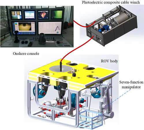
Figure 1. The hardware system of ROV. ROV: Remotely operated vehicle.
Main technical parameters of the developed remotely operated vehicle
| Technical parameters | Value |
| Size Thrusters Weight Maximum working depth Maximum forward speed Navigation sensor Detection sensor Supply voltage Operational capability | Length: 1.6 m, Width: 1.2 m, Height: 0.98 m Horizontal: 6.5 kW × 4, Vertical: 2.4 kW In air: 380 kg, In water: 4 kg 300 m 2.2 m/s INS, DVL, depth gauge, altimeter Multi-beam forward-looking sonar, Cameras 310 VDC Seven-function manipulator |
3.1 CPU systems
Onshore console, ROV body and seven-function manipulator all have their own CPU systems. The distribution of each CPU system is shown in Figure 2.
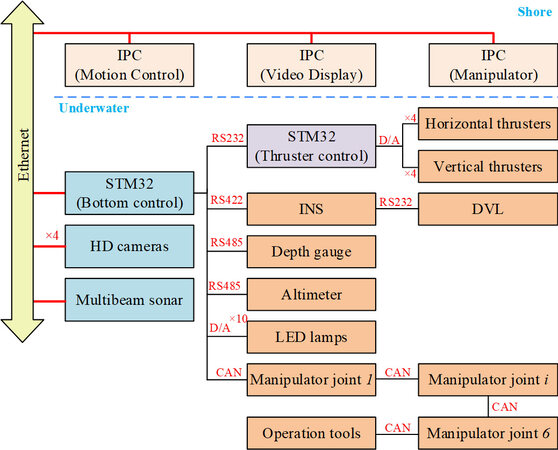
Figure 2. CPU systems distribution. INS: Inertial navigation system; DVL: Doppler velocity log; IPC: industrial control computer; HD: high definition; CAN: controller area network; LED: light-emitting diode; STM: SGS-THOMSON Microelectronics.
As shown in Figure 2, the Ethernet communication between the onshore console and the bottom controller of the ROV body is used. The information sent from the onshore console includes thruster control commands, manipulator control commands, etc. The information fed back to the onshore console includes the state information of the robot body and the state information of the manipulator.
The bottom control CPU developed by STM32 single chip microcomputer is the core of the ROV body. In order to control the thrusters, an additional STM32 single chip microcomputer is added. This is necessary as the bottom control CPU system is placed in the main control cabin while the power supply of the thrusters is in the power cabin. If the bottom control CPU sends control instructions to the thrusters directly, one of two cases will happen. On the one hand, the control commands of 8 thrusters are connected to the power cabin, and then integrated with the thruster power supply to connect to the thrusters. On the other hand, cables are led out from the power supply cabin and the main control cabin respectively to connect with the thrusters. It is conceivable that the number of cable connections will be increased in either case. An additional CPU system is added in the power cabin to receive and convert the thruster control commands. This can effectively reduce the number of connectors. Although such processing will cause a certain signal delay, the control cycle of ROV is generally longer, and the millisecond signal delay can be ignored.
The motor of each joint of the seven-function manipulator adopts a modular design. Each joint motor is integrated with DC brushless motor, harmonic reducer, resolver, motor driver, etc. At the same time, it is also equipped with a CPU system, such that the closed-loop control of angle can be realized. Each joint is connected with ROV bottom control CPU through controller area network (CAN) bus to realize joint angle command sending and feedback.
The onshore console is equipped with three industrial control computers (IPC). The first IPC (motion control IPC) is mainly responsible for the underwater motion control of the ROV body. It is equipped with a multi-functional control handle, which can realize the control of four degrees of freedom - surge, sway, yaw and heave. In addition, the control of heading, depth, positioning and other control functions can be realized by combining the multi-function buttons. The video display IPC is mainly responsible for the image display of high definition cameras and multi-beam forward-looking sonar. Finally, the manipulator IPC is mainly responsible for the control of the seven-function manipulator, which can realize master-slave control.
3.2 Thrusters
The ROV body is equipped with four (4) horizontal thrusters and four (4) vertical thrusters.
In terms of the horizontal thruster arrangements, the maximum speed design index is considered. The thrusters adopt the classical arrangement as shown in Figure 3. The angle between the thrusters and the forward direction is set at α = 30°. The horizontal thruster selected for ROV has a maximum forward thrust of 120 kgf and a maximum reverse thrust of 60 kgf. With regards to the layout of horizontal thrusters, the maximum forward thrust of ROV is 415 kgf, the maximum backward thrust of ROV is 207 kgf, and the maximum lateral thrust is 180 kgf.
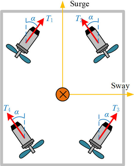
Figure 3. The horizontal thruster arrangement.
Due to the small size of the ROV body, the interference between horizontal thrusters and vertical thrusters is inevitable in the layout. First, the distance between the front and rear of the vertical thrusters is arranged as 0.48 m, while the horizontal thrusters are arranged on the front and rear sides. Then, through hydrodynamic analysis, the position between the front and rear of the horizontal thrusters and the camber angle of the vertical thrusters are gradually adjusted, so as to minimize the interference between horizontal thrusters and vertical thrusters.
3.3 Sensors
In addition to the conventional depth control and heading control functions, the designed ROV has the main advantage of underwater hovering control function. In order to realize this function, ROV is equipped with an inertial navigation system (INS), a doppler velocity log (DVL), depth gauge, altimeter and other sensors. By integrated navigation of INS and DVL, the underwater position information, the heading information and the attitude information of ROV can be obtained in real time. The integrated navigation system is shown in Figure 4.
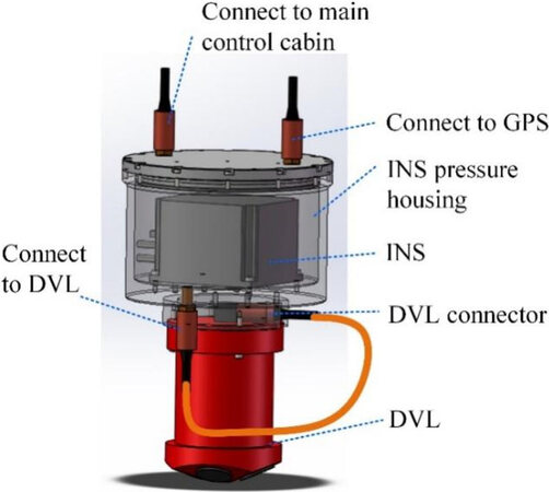
Figure 4. The integrated navigation system. INS: Inertial navigation system; DVL: Doppler velocity log.
3.4 Seven-function manipulator
According to the conventional definition of an underwater manipulator, the seven-function manipulator mainly includes a manipulator body with six degrees of freedom and an end operation tool[18]. The designed seven-function manipulator is installed on the front side of the ROV body. Its maximum operating range exceeds 1.5 m. The manipulator can carry 10 kg underwater when extending to the maximum range. The manipulator adopts the classical six degrees of freedom configuration scheme, as shown in Figure 5, which is convenient for forward and inverse kinematics solutions. The shape of the manipulator and the coordinate system of each connecting rod are shown in Figure 5. The connecting rod parameters obtained according to the D-H coordinate system are shown in Table 2. The parameters in the table are defined according to the standard D-H coordinate system.
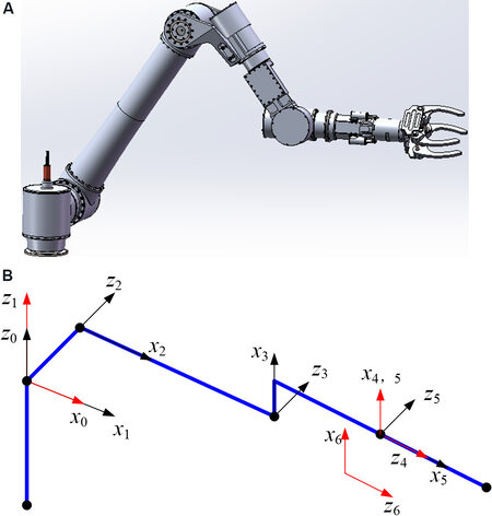
Figure 5. The shape of the manipulator and the coordinate system. (A) The shape of the manipulator; (B) the coordinate system.
The connecting rod parameters
| i | ai-1 | αi-1 | di | θi | Variable range | Value/mm |
| 1 | 0 | 0° | 0 | θ1 (90°) | -120°-60° | a2 = 796.5 |
| 2 | 0 | -90° | d2 | θ2 (0°) | -70°-90° | a3 = 118 |
| 3 | a2 | 0° | 0 | θ3 (-90°) | 0°-180° | d2 = 124 |
| 4 | a3 | -90° | d4 | θ4 (0°) | -160°-160° | d4 = 433 |
| 5 | 0 | 90° | 0 | θ5 (0°) | -90°-90° | |
| 6 | 0 | -90° | 0 | θ6 (0°) | -160°-160° |
The manipulator consists of six modular joint motors. In this paper, taking the shoulder joint base motor as an example, the composition is presented. Figure 6 shows the cross-sectional view of the shoulder base motor.
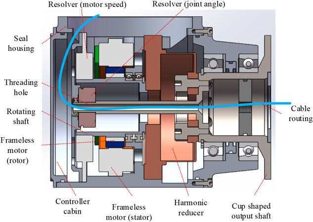
Figure 6. The cross-sectional view of the shoulder base motor.
As shown in Figure 6, the main components of the joint motor include:
(1) Driving parts: Frameless DC brushless motor is selected, which can effectively reduce the size of the joint motor. The motor stator is directly bonded with the sealed shell to ensure heat dissipation better.
(2) Reduction parts: Harmonic reducer is selected, which has small volume and is lightweight, but with a large reduction ratio. In this manipulator, the reduction ratio of the selected reducers exceeds 120. The harmonic reducer only includes three components: a basic wave generator, flexible wheel and rigid wheel, which can further reduce the size requirement.
(3) Detection parts: Two resolvers are selected to detect the motor speed and output shaft angle respectively, so as to realize the double closed-loop control of the motor output.
(4) Dynamic sealing parts: The joint motor adopts a cup-shaped output shaft to facilitate connection with the next joint. A double-layer sealing ring is arranged outside the shaft to ensure the underwater dynamic sealing performance.
The structure of other joints of the manipulator is similar to that in Figure 6. Each joint has a built-in controller, which can realize the closed-loop control of joint angle. The joints are connected by 6-core cables. Among them, the 2-core cable is used as the positive pole of the power supply, the 2-core cable is used as the negative pole of the power supply, and the other 2 cores are used for CAN communication. The modular characteristics of each joint enable it to be combined freely, which simplifies the electrical system of the manipulator.
4. CONTROL SOFTWARE ARCHITECTURE
The software control of the designed ROV is mainly executed on the onshore console. It includes the motion control of the ROV body and the control of manipulator operation. Relatively speaking, the ROV body and manipulator mainly execute the commands sent by the onshore console and feedback their respective state information. As shown in Figure 2, the control commands of the manipulator need to be sent through the bottom control CPU of the ROV body, which makes it possible to perform the cooperative operation between ROV and the manipulator. Here, the control software architecture of the ROV body will be introduced.
ROV body has the operation ability of remote control and automatic control, as well as the hybrid control ability of the combination of the two. Here, the traditional hierarchical control architecture is used for software system development. The control software architecture is shown in Figure 7.
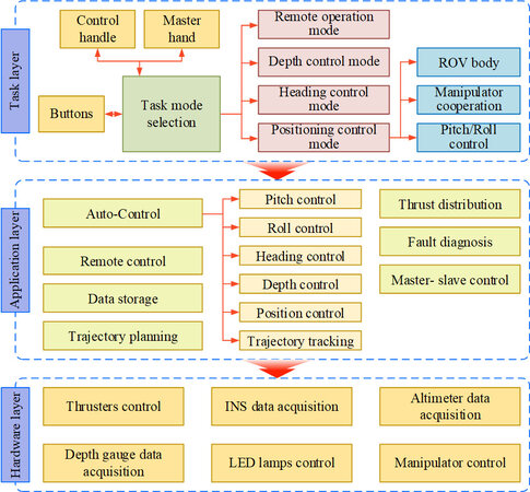
Figure 7. The hierarchical control software architecture. ROV: Remotely operated vehicle; INS: inertial navigation system; LED: light-emitting diode.
Vertically, the control software architecture is divided into three layers: (1) task layer; (2) application layer; and (3) hardware layer.
The hardware layer is mainly responsible for the information interaction with the underlying hardware system, which mainly runs in the underlying control CPU of ROV body and each joint motor of manipulator. In information collection, interrupt processing is mainly used to ensure real-time performance. In control command sending, the command is mainly sent by a timer. The control cycle of thrusters and manipulator joint motors are set as 25 ms, and then closed-loop control is carried out by the built-in controllers of thrusters and manipulator joint motors respectively.
The application layer is mainly responsible for realizing various functional modules, including remote control module, automatic control module, data storage module, trajectory planning module, thrust distribution module and fault diagnosis module. Each module of the application layer mainly runs in the motion control IPC of the onshore console. Each functional module adopts multi-threaded programming technology to ensure parallel processing ability. In actual operation, corresponding function modules can be selected according to the task mode set by the task layer. It should be noted that a fault diagnosis module is set in the application layer to detect the running state of the propeller in real time.
The task layer is mainly responsible for receiving the command information of the control handle, master hand and buttons on the onshore console, and selecting the corresponding task mode. For the designed ROV, its main task modes include the following:
(1) Remote control mode
The remote-control mode includes the remote-control operation of ROV body and the master-slave operation of manipulator.
The remote-control operation of ROV body is mainly controlled by the control handle of the onshore console (as shown in Figure 8A). The control handle can realize the movement of three degrees of freedom in the horizontal plane, corresponding to the surge, sway and yaw of ROV, respectively. At the same time, a small button is set on the upper part of the control handle, which can be used to control the heave of ROV. In this mode, the feedback information of the control handle is mapped to the force or moment of each degree of freedom, and then the thrust distribution module is used to get the control commands of the thrusters.
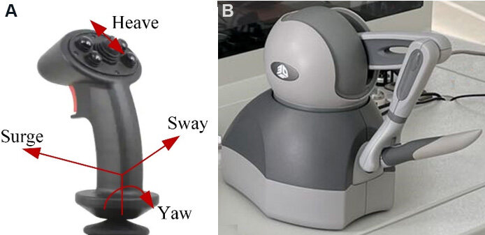
Figure 8. The input of the remote control. (A) Control handle; (B) master hand.
Take pushing the handle forward for surge control as an example, assuming that the pushing forward amplitude is 60%. According to Section 3.2, the maximum surge force of the ROV is 415 kgf. Therefore, corresponding to the handle signal, the surge force given by the thrusters should be 415 kgf × 60% = 249 kgf. According to the surge dynamic value, combined with the thrust distribution method given later, the expected thrust value of each thruster can be obtained.
The master-slave operation of the manipulator is mainly controlled by the master hand of the onshore console (as shown in Figure 8B). The master hand can realize the independent movement of 6 joints. Due to the fact that the layout of the connecting rod coordinate system of the master hand and the designed seven-function manipulator is basically similar, each joint of the master hand can be corresponded to each joint of the manipulator one by one. At the initial time, the angles qmi0 and qsi0 are recorded, respectively, where qmi0 is the ith joint of the master hand, and qsi0 is the ith joint of the designed seven-function manipulator. At time t, the angle qmit of the ith joint of the master hand is recorded again. At this time, the angle control command of the ith joint of the designed seven-function manipulator can be set as qsit= qsi0+ (qmit- qmi0). In this way, the master-slave control of master hand and the seven-function manipulator is realized.
(2) Automatic control mode
Automatic control mode includes depth control, heading control, position control and other modes. Among them, the position control mode can be further subdivided according to whether it cooperates with the manipulator or whether it carries out roll and pitch control. According to the needs of each control mode, the corresponding automatic control function module in the application layer can be configured.
In the process of control design, the establishment of an accurate model of the ROV can be suitable for the design of a high-performance controller. However, the developed ROV is mainly used as a working platform. In future applications, the operating equipment and load will change with the actual demand. Therefore, the Proportional Integral Derivative (PID) algorithm is directly used to design the controller; therefore, making the mathematical model is rather unnecessary. In the future, the performance of the controller can be improved by adjusting the PID control parameter, such as the fuzzy PID algorithm.
Taking the depth control mode as an example, according to the given depth control command, the PID controller is generally used to calculate the expected force of the heave degree of freedom in the carrier coordinate system. Then the control command of each vertical thruster can be calculated according to the thrust distribution module. However, in the depth control mode, for the situation that the automatic roll control and automatic pitch control modes are activated simultaneously, independent controllers need to be designed to have three degrees of freedom, and then the thrust distribution processing is carried out.
Consider the heading control mode as another example; this mode is generally only used for automatic control of yaw angle. Further applications of this are in use as hybrid control combined with control handle. In this mode, the desired torque of yaw freedom in the carrier coordinate system is obtained by the heading automatic controller, while the desired force of surge and sway degrees of freedom is generally determined by the control handle. At this time, the thrust distribution will be calculated according to the output value of the heading controller and the surge and sway feedback information of the control handle.
(3) Thrust distribution scheme
The output of the PID controller or the handle is the expected thrust/torque of each degree of freedom of ROV. The actual control signal is the thrust of the thruster, and then the control signal of the thruster is calculated according to the thrust. Therefore, thrust distribution is the process of calculating thruster thrust from the expected thrust/torque of each degree of freedom. In this scheme, specifically considering the horizontal thrusters, the thrust distribution scheme is discussed.
According to the horizontal thrusters’ layout scheme in Figure 3, the relationship between the thrusters thrust and the surge force, the swage force and the yaw torque can be obtained as:
where X is the surge force, Y is the sway force, N is the yaw torque, T1, T2, T3, and T4 represent the thrust of the front left, front right, rear right and rear left thrusters respectively, α is the angle between the thruster and the forward direction, and r is the force arm of the thruster relative to the origin of the carrier coordinate system.
According to the pseudo inverse of Equation (1), another equation emerges, thus:
The calculation speed of thrust distribution according to Equation (2) is fast. However, the following problems emerge. First, when the values of X, Y and N are large, the thrust signal calculated according to Equation (2) may exceed the feasible range. At this time, the calculated thrust value cannot be realized. Therefore, it can be recalculated by artificially reducing the values of X and Y while maintaining the value of N, that is:
The thrust distribution scheme has its advantage. Although it cannot meet the expected movement requirements, the heading control can be maintained. This meets the needs of practical application.
After one calculation according to Equation (3), if Ti still exceeds the feasible range, then it results in the continuous reduction of the expected surge and sway force values according to (3) until Ti is within the feasible range.
The above calculation process is simple to realize, and the calculation speed is fast, which is convenient for practical system applications. Of course, the method of target optimization can also be used for thrust distribution. Its distribution result is more reasonable, but the amount of calculation is large.
5. IMPLEMENTATION
After completing the development of the whole ROV hardware and software systems, the lake tests are carried out. The test performed include remote-control test, maximum speed test under remote control, depth control test, heading control test, hover control test, manipulator test, etc. In the remote-control mode, the motion of ROV is mainly controlled through the handle of the onshore console. This is similar to most ROV control methods. This paper mainly tests the automatic control ability of the ROV. This is also the biggest feature of the designed ROV compared with other ROVs of similar size. In this section, the test results of depth control, heading control and hover control will be introduced and analyzed separately.
As shown in Figure 9, the test environment of ROV is a lake with a length of 240 m and a width of 70 m. The maximum depth of the lake is about 8 m and the water flow is static. This provides good conditions for testing the maximum speed and heading control capability of ROV. There is a protruding platform in the lake, which facilitates the placement and recycling of ROV. The placement and recycling of ROV are shown in Figure 10.
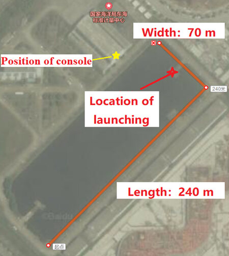
Figure 9. The test environment.

Figure 10. The placement and recycling of a remotely operated vehicle.
In order to test the depth control ability of ROV, two groups of depth trajectory tracking control experiments are performed. In the experiment, the ROV is controlled to move up and down within ± 1 m of the rated depth at the frequency of 0.005 Hz and 0.01 Hz, respectively. The variation equations of the target depth are as follows:
The results of the depth test are shown in Figure 11. The average values and mean square deviations of the tracking errors obtained from the test are presented in Table 3. The results show that the designed depth controller has good depth trajectory tracking control performance.
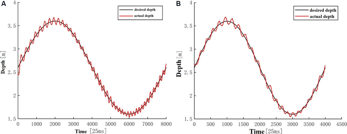
Figure 11. Results of depth trajectory tracking. (A) Depth trajectory 1; (B) depth trajectory 2.
Mean value and mean square deviation of depth trajectory tracking error
| Depth trajectory | Mean value | Mean square deviation |
| 1 2 | 0.0007 m 0.0008 m | 0.06 m 0.05 m |
In order to test the heading control ability of ROV, two groups of heading trajectory tracking control experiments are carried out. In the experiment, the ROV is controlled to move within 360° at 0.005 Hz and 0.01 Hz, respectively. The variation equations of target heading are:
The results of the heading test are shown in Figure 12. The average values and mean square deviations of the tracking errors obtained from the test are shown in Table 4. The results show that the designed heading controller has good trajectory tracking control performance in low frequency range, but the tracking control performance in high frequency range is slightly poor. We speculate that this is due to the simultaneous activation of the depth control function in heading control. This will cause interference between vertical thrusters and horizontal thrusters. The performance of heading controller should be further improved in the follow-up research, so as to enhance the anti-interference ability in a real environment.
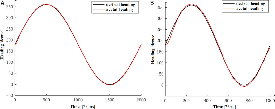
Figure 12. Results of heading trajectory tracking. (A) Heading trajectory 1; (B) heading trajectory 2.
Mean value and mean square deviation of heading trajectory tracking error
| Heading trajectory | Mean value | Mean square deviation |
| 1 2 | 0.12° 0.83° | 1.77° 6.43° |
As mentioned earlier, an important advantage of the designed ROV is its ability to hover underwater. Therefore, in this subsection, the underwater hover control is tested and the findings are discussed. The test results show that the ROV has high hovering control accuracy. It can converge quickly even after external interference is applied. Hover control results are shown in Figure 13. The results show that the hovering control accuracy can reach the range of ± 10 cm, and even be controlled within ± 5 cm after stabilization. This provides a guarantee for observation and operation under complex flow fields.
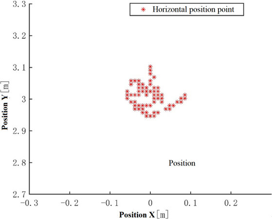
Figure 13. Results of hover control.
6. CONCLUSION
In this paper, a medium-sized ROV has been developed and tested. Compared with the existing common medium-sized ROV, the main features are that it is equipped with a seven-function electric operation manipulator and has the ability of underwater automatic hovering control function. In this paper, the control hardware architecture and control software architecture of the ROV have been discussed in detail, and the findings from rigorous tests for evaluation of the automatic control ability of the ROV are presented. The results from the various experiments show that the developed ROV sufficiently meets the design requirements and technical index requirements. However, there are still some deficiencies in the control accuracy of heading control. Further adjustment of the controller is required, which is included in the future research agenda.
DECLARATIONS
Authors’ contributions
Performed data analysis and interpretation, manuscript writing, and material support: Wang JH
Performed conception and design of the study: Chu ZZ
Availability of data and materials
Not applicable.
Financial support and sponsorship
This work was supported in part by the National Natural Science Foundation of China under Grant (No. U2006228) and in part by the Shanghai Science and Technology Innovation Action Plan under Grant (No. 19040501600).
Conflicts of interest
Both authors declared that there are no conflicts of interest.
Ethical approval and consent to participate
Not applicable.
Consent for publication
Not applicable.
Copyright
© The Author(s) 2022.
REFERENCES
1. Lück T, Kvasnicka V, Lück A. [Remotely operated underwater vehicles used in water rescue]. Unfallchirurg 2021;124:977-83.
2. Karimi HR, Lu YY. Guidance and control methodologies for marine vehicles: a survey. Control Eng Pract 2021;111:104785.
3. Capocci R, Dooly G, Omerdić E, Coleman J, Newe T, Toal D. Inspection-class remotely operated vehicles - a review. JMSE 2017;5:13.
4. White J, Horn L. ROV sample collection skid collecting scientific samples with observation-class ROV. Sea Technol 2017;58:31-4.
5. Zain ZM, Noh MM, Ab Rahim KA, Harun N. Design and development of a remotely operated vehicle with new maneuvering method. Indian J Geo-Marine Sci 2017;46:2519-26.
7. Sakagami N, Hirayama K, Taba R, et al. Development and field experiments of a human-portable towed ROV for high-speed and wide area data acquisition. Artif Life Robotics 2021;26:1-9.
8. Kim T, Yuh J. Development of a real-time control architecture for a semi-autonomous underwater vehicle for intervention missions. Control Engineering Practice 2004;12:1521-30.
9. Yu CY, Xiang XB, Maurelli F, Zhang Q, Zhao R, Xu GH. Onboard system of hybrid underwater robotic vehicles: integrated software architecture and control algorithm. Ocean Eng 2019;187:106121.
10. Gusev AL, Golovina ES. About the development of a technological complex with a manipulator for an unmanned underwater vehicle. IOP Conf Ser Mater Sci Eng 2019;537:032043.
11. Sun YS, Ran XE, Zhang GC, Wu FY, Du CR. Distributed control system architecture for deep submergence rescue vehicles. Int J Naval Architecture Ocean Eng 2019;11:274-84.
12. Li Z, Tao J, Sun H, Li J, Luo Y, Deng Z. Analysis of cable force on steady-state motion of remotely operated vehicle for reaction pool underwater welding. Int J Adv Robot Syst 2019;16:172988141985729.
13. Chin CS, Jia J, Hay King Chiew J, et al. System design of underwater battery power system for marine and offshore industry. J Energy Storage 2019;21:724-40.
14. Hernando M, Alonso M, Prados C, Gambao E. Behavior-based control architecture for legged-and-climber robots. Applied Sciences 2021;11:9547.
15. Malekzadeh MS, Queißer JF, Steil JJ. Multi-level control architecture for Bionic Handling Assistant robot augmented by learning from demonstration for apple-picking. Advanced Robotics 2019;33:469-85.
16. Angelini F, Della Santina C, Garabini M, Bianchi M, Bicchi A. Control architecture for human-like motion with applications to articulated soft robots. Front Robot AI 2020;7:117.
17. Zhang Y, Dai K, Xu C, Kang Y, Dai Z. Multiple sampling PSC-PWM with hierarchical control architecture for MMC-DSTATCOM. IET Electr Power Appl 2019;13:1431-40.
Cite This Article
Export citation file: BibTeX | RIS
OAE Style
Wang J, Chu Z. Developing and testing a remotely operated vehicle with a seven-function manipulator. Complex Eng Syst 2022;2:2. http://dx.doi.org/10.20517/ces.2022.01
AMA Style
Wang J, Chu Z. Developing and testing a remotely operated vehicle with a seven-function manipulator. Complex Engineering Systems. 2022; 2(1): 2. http://dx.doi.org/10.20517/ces.2022.01
Chicago/Turabian Style
Wang, Jiahui, Zhenzhong Chu. 2022. "Developing and testing a remotely operated vehicle with a seven-function manipulator" Complex Engineering Systems. 2, no.1: 2. http://dx.doi.org/10.20517/ces.2022.01
ACS Style
Wang, J.; Chu Z. Developing and testing a remotely operated vehicle with a seven-function manipulator. Complex. Eng. Syst. 2022, 2, 2. http://dx.doi.org/10.20517/ces.2022.01
About This Article
Copyright

Data & Comments
Data
0

 Cite This Article 12 clicks

 Like This Article 40
likes
Like This Article 40
likes


Comments
Comments must be written in English. Spam, offensive content, impersonation, and private information will not be permitted. If any comment is reported and identified as inappropriate content by OAE staff, the comment will be removed without notice. If you have any queries or need any help, please contact us at support@oaepublish.com.