
PEM fuel cell system to extend the stack life based on a PID-PSO controller design

Abstract
In this paper, the nonlinear model of polymer exchange membrane (PEM) fuel cell system is first extracted and then tested and evaluated for various temperatures and pressures. With the severe nonlinear characteristics of the PEM fuel cell system, using the proportional-integral-derivative (PID) controller for the linear model of the PEM fuel cell system could not guarantee robust control under parametric uncertainty and severe load fluctuations. The use of a linear model-based controller increases the pressure in both the anode and cathode areas, which in turn induces a high pressure difference across the polymer membrane, thus reducing the lifespan of the fuel cell. The proposed method uses the particle swarm optimization (PSO) algorithm, taking into account practical parameters, to design a PID controller for a nonlinear model of the fuel cell. Comparison of the results obtained from the conventional PID controller and the proposed PID-PSO structure shows that PID-PSO can desirably guarantee the specifications of overshoot, transient time, and settling time for a defined pressure difference across the anode and cathode plates.
Keywords
1. INTRODUCTION
In recent years, the fuel cell system has received increasing attention as one of the sources of electric power generation. A fuel cell is a type of electrochemical cell that directly converts energy from a chemical reaction to electrical energy. Various types of fuel cells exist, capable of generating from few milliwatts up to several megawatts of electric power. This electric power generator has many applications in portable electrical devices, transportation vehicles, distributed generation supply systems, etc. The polymer membrane fuel cell is a popular type of fuel cell, which, due to its solid membrane and moderate working temperature, can provide more flexibility over the other types[1-4]. Due to the complexity and extremely nonlinear structure of fuel cell systems, the problem of controlling a “fuel cell” is considered a challenge and provides many research opportunities for researchers[5].
In a fuel cell system, the load current is regarded as external and measurable turbulence. Therefore, the use of a feed-forward controller is the first step in designing a fuel cell controller. Such controller is designed either as a lookup table in the case of a static feed-forward controller or as a transfer function in the case of the dynamic feed-forward control approach. Due to the presence of uncertainties in the measurements of peripheral sensors such as stack temperature, cathode volume, atmosphere pressure, and electric resistance of the motor, as well as the existence of unknown input turbulence, the sensitivity of the system is considered unity across all frequencies[2]. Among other types of feedback controllers, state-feedback controllers and linear quadratic regulators can be mentioned, which are utilized to maintain air stoichiometry and avoid fuel starvation. The system designed using state feedback guarantees tracking of the reference input, such that the effect of turbulence and the closed-loop response modeling error is damped[3]. The classic approaches exercised by researchers[2,6] involve linear design methods and require either detailed information about system parameters or an estimate of the model uncertainties[7]. Conventional controllers often lack the satisfactory capability of functioning against large changes in system and load parameters, that is, they are prone to become unstable at points other than the operating point. Because of the highly nonlinear characteristics of the polymer exchange membrane (PEM) system, there are unknown uncertainties due to the modeling error and the parametric (fatigue in fuel cell components and changes in ambient conditions) uncertainties[3]. Thus, the implementations of the nonlinear controllers in[8-11] solve these problems as low reliability and short lifespan. Therefore, it is necessary to improve the fuel cell peripheral systems by utilizing proper stack materials and innovative control systems to reduce costs while achieving faster dynamic responses, long durability, and energy optimization. One of the main issues in developing a strategy for robust control of a fuel cell is how to tackle internal and external turbulences and uncertainties. Nonlinear controllers built around feedback linearization enjoy such characteristics as dynamical range boosting and transient behavior improvement in the fuel cell system controller. Nevertheless, the controller should be designed in a way that can provide adequate performance against a wide range of severe system nonlinearities.
The feedback linearization method has been used as a nonlinear control design approach for the investigated fuel cell system. In this strategy, the nonlinear dynamic is estimated by a linear dynamic, and a linear controller (error tracking) is subsequently utilized to design the suitable controller. Some studies employ the multi-input multi-output model to minimize pressure difference ΔP. In these methods, a nonlinear controller is design by linearization of feedback[8,9]. The control goal of these models is to induce a slight pressure on the anode side as well as a slight pressure on the cathode side, to prevent damage to the catalyzer and the membrane electrode assembly (MEA), and thereupon to increase the stack lifetime. The controller is developed based on linear control theory and using the pole placement technique. The main drawback of the above methods is that they require detailed knowledge about some system parameters. In situations with parametric uncertainties or non-modeled dynamics, there is no guarantee of robustness.
In Refs.[10-13], sliding mode nonlinear control methods are utilized to maintain and control the gas pressure in the fuel cell system. The downside of these sliding mode methods is the chattering and variations in set point, which cannot be completely eliminated but can be reduced by applying some techniques. The chattering effect in fuel cell pressure control causes damage to MEA and actuators.
The popularity of the sliding mode control method is because of its applicability to a class of nonlinear systems in the global sense and the issues of performance and stability robustness to modeling uncertainties and disturbances. The major advantage of sliding mode is low sensitivity to plant parameter uncertainties and external/internal disturbances, which eliminates the necessity of exact modeling[14,15]. However, the discontinuous control in sliding mode control causes high-frequency switching. Therefore, high-frequency vibrations or “chattering” in the output damage actuators. One of the most beneficial techniques for decreasing chatter is higher-order sliding mode control, which has been developed to decline this phenomenon and maintain robustness and the finite-time convergence properties of the classical sliding mode under load variations and parametric uncertainties. However, the conventional sliding mode technique induces an undesirable chattering effect in control signals due to the sign function. This phenomenon leads to system instability or actuator damage.
Recently, the direct current (DC) microgrid system for electric vehicles with energy-consuming homes was proposed by Savrun et al.[16]. In this system, a hybrid fuel cell/battery system with DC/DC converter is used. The designed system has a fuel cell and a battery that supply an electric vehicle as energy units to manage electrical energy for the vehicle-to-home concept.
İnci[17] proposed an energy management system for the economical and optimum operation of grid-integrated renewable energy systems. A control strategy is proposed based on perturbing and observing maximum power point tracking, and it is purposed to improve the system efficiency under the grid-connection and grid-failure modes of the fuel cell system. Optimum energy generation for local loads under grid-failure mode and enhancement of electrical energy quality at the load-side are advantages of the proposed method.
İnci et al.[18] suggested a modified energy management method based on the photovoltaic/fuel cell system to support balancing in grid connection. For this aim, a control strategy is proposed to improve the grid quality under unbalanced loading conditions.
Rakhtala[19] proposed an intelligent controller as a self-tuning fuzzy logic proportional-integral-derivative (PID) controller. The self-tuning fuzzy logic PID controller to control the excess oxygen ratio is proposed. This closed-loop system adjusts the airflow rate in the cathode input, and the control aim is to keep the oxygen ratio in its operating range by a compressor.
In 2015, Swain and Jena[20] used a PID controller to regulate anode/cathode pressure, which requires linearization to near the operation point, is not at all robust to the load turbulence and variations, and is responsive to the system tracking in the operation point only. The results of our simulations indicate that there exist practical limitations when using these control coefficients, since the applied control coefficients unveil shortcomings and limitations during practical implementation. The selected control coefficients only consider control and maintaining the voltage at a fixed reference. In other words, such practical limitations as oxygen pressure control (PO2), hydrogen pressure control (PH2), and the pressure difference across membrane (ΔP) are not considered.
Simulations results indicate very high pressure (beyond membrane tolerance) during the action, which in turn points out the big drawback of using the mentioned control technique. Hence, regulation of the output voltage requires a control methodology that incorporates such considerations as PO2 and PH2 pressure controlling as well as ΔP pressure difference within a particular range that satisfy practical limitations. In this study, we made efforts to regulate PID controller coefficients for the PEM fuel cell system using the particle swarm optimization (PSO) algorithm and defining a suitable cost function based on practical considerations.
The remainder of this paper is organized as follows. In Section 2, the dynamic model of PEM fuel cell is presented. In Section 3, the PSO as an intelligent optimization method used in our study is presented and explored. The proposed controller called PID-PSO PEM, which meets the practical considerations of a fuel cell, is introduced in Section 4, with the results appearing in Section 5. The paper ends in Section 6 with the conclusions.
2. DYNAMIC MODELLING OF PEM
A fuel cell is a type of electrochemical cell, in which the energy resulting from the chemical reaction is directly converted into electrical energy. In the fuel cell, hydrogen and oxygen are fed to the anode and cathode, respectively. Each hydrogen atom is made from a proton and an electron, and giving away that electron leaves a single proton (H+) and makes it capable of passing through the electrolyte. As a result, the H+ ions move across the electrolyte, and the electrons arrive at the cathode via an external connection. Reaching the cathode, these electrons ionize the oxygen atoms generating anions in the electrolyte, which in turn combine hydrogen protons and produce water molecules that leave the system. Considering the sensitivity of the polymer membrane to the pressure change variation, among the most important goals in the fuel cell control procedure are maximizing the lifespan of the stack and avoiding damaging the membrane. Therefore, partial control of hydrogen and oxygen pressures as the key system parameters is among the most important control targets, aiming to prevent deterioration of the polymer membrane. In this system, the control goal is minimizing the pressure difference ΔP between partial pressure on the anode side and partial pressure on the cathode side. The main objective of keeping ΔP at a very small changing value is to prevent damaging the membrane, thus increasing the lifespan of the fuel cell system[15,20]. Since large deviation (about 500 millibars) in partial pressures of hydrogen and oxygen can damage the membrane of the fuel cell, it is necessary to design a suitable controller for the elimination of such deviations occurring during times when the load is changed, or turbulences emerge[21,22]. It should also be noted that, as the voltage of fuel cell is a function of pressure, the precise and proper control of anode/cathode side pressures is needed in a way that detrimental voltage drop of the fuel cell is avoided. Under standard conditions of 25 °C and one atmospheric pressure, the ideal standard potential of 1/229 V is obtained from a hydrogen/oxygen fuel cell system by producing water. Because of the irreversible voltage drops occurring in fuel cell systems, the actual voltage of a fuel cell is normally less than the ideal voltage value. That is, due to irreversible losses, the consumable voltage of fuel cell falls below the ideal equilibrium point.
In addition, the instantaneous Nernst voltage (ENernst) is written as below[4,12,23,24]:
The PEM fuel cell voltage is defined as the sum of three thermodynamic potential terms of activation losses, ohmic losses, and concentration losses. The voltage-current polarization curve of a fuel cell is depicted in Figure 1, representing these losses.
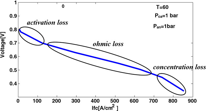
Figure 1. The voltage-current polarization curve of the fuel cell.
In the following sections, the above-mentioned losses are presented separately in more detail.
2.1 Activation voltage loss
Activation voltage loss is dependent upon the electrochemical reaction occurring on the surface of electrode since, in the case of any reaction, the reactor needs to overcome an existing activation potential barrier. In other words, the activation voltage loss is related to the rate of chemical reaction occurring on the electrode surface, which in turn requires the consumption of some energy to create bounds between hydrogen and oxygen atoms. The formula for the activation voltage loss is given as:
According to Henry’s law, the concentration of oxygen dissolved on the gas-liquid interface is written as[20,25,26]:
In addition, the relation between internal resistance of the fuel cell and activation voltage loss is:
2.2 Ohmic voltage loss
Ohmic voltage loss occurs due to the resistance against ions’ flow across the electrolyte, as well as the ohmic resistance of electrodes against electrons. Ohmic voltage loss results from the transfer of electrons through the separation between collector layers, carbon electrodes, and the resistance imposed on proteins when passing through the membrane. The internal resistance of fuel cell per ohms and ohmic losses can be written as[4]:
Thus, the ohmic induced losses can be obtained from:
2.3 Concentration voltage loss
Once reactants are consumed at the anode and cathode, they need to be replaced by fresh reactants, so that the reaction continues. Normally, the replacement process has some inertia, meaning it will not occur immediately. If the fuel cell anode is supplied by the relevant fuel, a partial pressure drop of the fuel will occur due to its partial consumption in response to the electric current drawn from the fuel cell. This drop in pressure depends on the current drawn from the cell as well as the physical properties of the fuel feeding system (speed of the pump). The concentration voltage loss in the fuel cell system is given as[4]:
The dynamics of the fuel cell voltage is modeled by a capacitor with a capacitance of C. This capacitor models the double charge layer and is connected in parallel with activation resistor[4]:
2.4 Equivalent circuit model for fuel cell
Based on the above explanations, the equivalent circuit model of Figure 2 can be considered for a fuel cell. Figure 2 shows an equivalent circuit model of the PEM fuel cell, and voltage fuel cell (VFc) is the terminal voltage of the fuel cell. Rohmic, Ract, and Rconc are voltage losses that are shown by resistances. The low dynamics of the fuel cell voltage is modeled by a capacitor C. E is the Nernst voltage (ENernst) and open circuit voltage.
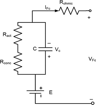
Figure 2. Equivalent circuit model of the fuel cell.
A fuel stack is formed by linking several fuel cells in series to increase the overall output voltage. As a result, the overall stack voltage is simply calculated by considering the number of fuel cells connected in series, that is:
where Ncellstands for the number of cells connected in series. Te is the amounts of consumed oxygen and hydrogen in a fuel cell, which depends on their input flow, output flow, current drawn from the fuel cell, and the volumes of electrodes. For the anode side, the following relation formulates the anode pressure[4,25]:
In the above, ṁ is the flow of fuel fed into the moisturizer and Vais the volume of fuel intake per m3. A stands for the channel space, while U quantifies the rate of fuel consumption. Finally, ρ, F, R, and T represent the molar concentration, Faraday constant, universal constant of gases, and the temperature of fuel cell in Kelvins (K), respectively. A similar relation exists as given below, governing pressure changes on the cathode side[4]:
In this relation, VC is the cathode volume for air intake per cubic meter[27,28]. The model parameters of the fuel cell are given in Table 1.
Specifications and operational parameters of the fuel cell[28]
| Number of cells: n | 37 |
| Open circuit voltage: V0 | 1.032 V |
| Anode volume for fuel intake | Va = 0.005 m3 |
| Cathode volume for fuel intake | Vc = 0.01 m3 |
| System temperature | 328 Kelvin |
| Universal constant of gases: R | 8.314 (J/mol-K) |
| Faraday constant: F | 96485 (C/mole) |
| Active membrane area: Afc | 232 cm2 |
| Exchange flow density: Jmax | 0.062 A cm-1 |
| Ohmic resistance of fuel cell stack: Rint | 2.45 × 10⁻⁴ |
| Concentration loss constant: B | 0.044777 |
| Partial pressure of each gas inside | |
| i | Output current density |
| i0 | Exchange current density |
| Ma | Molar mass of air |
| MO2 | Molar mass of oxygen |
| MN2 | Molar mass of nitrogen |
3. PARTICLE SWARM OPTIMIZATION
The PSO algorithm is inspired by the swarm behavior of groups of animals such as birds, fishes, and insects and offers a method of optimization[29]. PSO involves a group of particles moving in an n-dimensional space. This n-dimensional space provides a solution space for the optimization problem in hand, whose dimensions may contain possible solutions for the problem. In the search space, every particle has a location  ; corresponding to a possible solution for the problem. In addition, each particle has a velocity
  . Moreover, each particle stores in some memory the best private location
  obtained so far by that particle, as well as the best global location
  obtained so far among all particles. In each iteration, the value of the best global is shared among all particles, and particles try to move towards the best location found in the search space. More specifically, the velocities of particles are updated in time steps of t, which in turn are added to the previous location values so that all particles can move to their new locations. Thus,
In the relation above, v, X, and t represent velocity, displacement, and the steps towards optimization, respectively. In PSO, the newly updated velocity is obtained from a previous velocity using the following relation:
Where U(a, b) is a random variable of uniform distribution on the interval [a, b]. ω is a parameter known as inertia coefficient[29], which controls the contribution of the previous velocity to the determination of new velocity. In addition, ϕ1 and ϕ2 represent the importance of p(t) and g(t), respectively. Moreover, in all iterations, the velocity vector v(t) of all particles is limited by an upper limit parameter vmax. PSO is initiated by assigning all particles random coordinates from the search space based on a uniform distribution. The initial particle velocities are also randomly drawn for the interval [-vmax,vmax].
The most important issue to consider when designing optimization algorithms, and intelligent optimization algorithms in particular, is the determination of a suitable cost function for optimization. The choice of an inadequate cost function may grant higher priorities throughout the optimization process to the false solutions and therefore hugely affects obtaining the optimum solution.
4. CONTROLLER DESIGN BASED ON THE PEM FUEL CELL CONSIDERATIONS
PID controllers have been widely used in many applications for output regulation. A block diagram of the PID controller is shown in Figure 3.
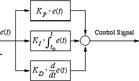
Figure 3. Transfer function of the proportional-integral-derivative controller.
In the figure above, KP, KI and KD are the proportional, integral, and derivative coefficients, respectively. It should be noted that the improper choice of these coefficients can severely degrade the operation of the system under control. One of the main limitations in utilizing PID controllers is how one should set these coefficients to achieve the best controlling state[29]. Another approach is to use a nonlinear system itself and directly design a PID controller employing intelligent methods; this is the approach utilized in this work. In the proposed method, the PSO algorithm is used to find the best PID coefficients. The block diagram structure of the utilized fuel cell as well the controllers is shown in Figure 4.
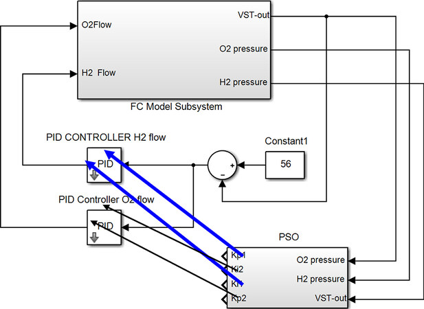
Figure 4. Controller block diagram for the proposed structure. PID: Proportional-integral-derivative; PSO: particle swarm optimization.
As shown in Figure 5, two PID controllers were initially envisaged for the proposed system, which hold, respectively, the roles of controlling hydrogen and oxygen flows in the fuel cell. Studies indicate that, considering the physical structure of researched fuel cell, the existence of derivative coefficients within controllers could provoke system instability[30]; therefore, by eliminating derivative coefficients, PID controllers are transformed to PI controllers. Since two coefficients are considered for each controller, the optimal selection of four integral and derivative coefficients creates a challenging problem. In the proposed system, this issue is dealt with by the use of the PSO algorithm. The definition of a suitable cost function is the most important factor for the success of optimization algorithms. In the proposed system, some constraints and criteria are considered for the building of the cost function, which are presented in the following.
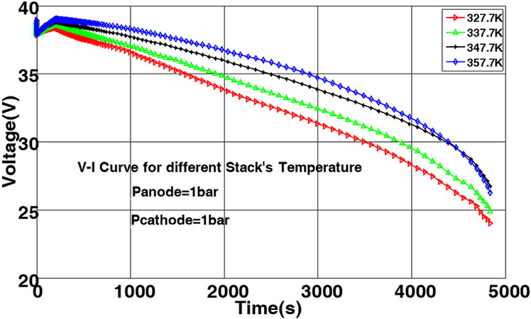
Figure 5. The polarization curve of the model for various temperatures.
4.1 Error integral criterion
The error integral criterion is adopted as a suitable measure for the performance evaluation of control systems. Different versions of this measure are proposed in the literature[31]. Our proposed system utilizes one of the most popular versions of the error integral criterion, as defined by the following relation:
Since the corresponding system response is of a slow decaying type, the ISTE measure provides the most adequate choice among various versions of error integral criteria[1].
4.2 Oxygen and hydrogen pressures (practical parameters)
Oxygen pressure (PO2) and hydrogen pressure (PH2) are two of the most important parameters existing in fuel cells and are included as constraints to the optimization stage of this study. The pressures of these gases are considered in two ways. Initially, for both pressures, a maximum value of 8 bars during the transient period (first 10% of the response) is considered, followed by a maximum pressure constraint of 6 bars for the rest of the response. In other words, all of the solutions that do not satisfy the given constraints are eliminated from the body of possible solutions. Besides the maximum pressure constraints, pressure differences (ΔP) of these two gases are two more important parameters that should be taken into account. In fact, some hardware limitations, such as the presence of a membrane between the anode and cathode, make the negligible difference among oxygen and hydrogen pressures both serious and preferable. The pressure difference between oxygen and hydrogen ΔP is incorporated into the cost function in three ways. To this, the population of PSO is categorized with respect to ΔP at three levels of ΔP > 4, 2 < ΔP < 4, and ΔP < 2. Populations with ΔP values exceeding 4 bars are assigned with a cost function value of infinity and eliminated as unfit solutions. In addition, the populations producing values between 2 and 4 bars affect the cost function directly. Finally, the effects of populations with values below 2 bars are considered as zero in the cost function. Thus, the overall cost function is formulated as follows:
In the above equation, z1 and z2 control limitations on the pressures of oxygen and hydrogen gases, respectively. To eliminate the populations exceeding the maximum pressure constraints, their corresponding z1 and z2 parameters are set to infinity. In addition, z3 is used to control ΔP. For ΔPs exceeding 4 bars and less than 2 bars, their corresponding z3s are set to infinity and zero, respectively. Finally, for ΔP ∈ [2,4], we consider z3 = ΔP.
5. SIMULATION AND RESULTS
In this section, we first present the simulation results for the proposed fuel cell model across various temperatures and pressures to validate the performance and evaluate its polarization curve. The performance of the designed controller is evaluated in the following.
5.1 The effect of cathode temperature on the performance of fuel cell
A 500-watt fuel cell was considered in the first simulation at a constant pressure condition (1 bars for cathode and anode), various temperatures, and for currents up to a 25 A. The polarization curve of the fuel cell is obtained by applying a step current, which is plotted in Figure 5 against different temperatures.
As shown in Figure 5, an increase in temperature elevates the polarization curve; thus, it can be concluded that temperature increases add to the current and voltage taken from the stack. In addition, the voltage drops over time is apparent for all temperatures.
5.2 The effect of cathode pressure on the performance of fuel cell
In this section, we present the results of another simulation carried out to evaluate the effect of cathode side pressure on temperature, while the anode side pressure was maintained at a fixed value. In this simulation, a 1 A current was again applied to the fuel cell. Since our goal was to study the effect of cathode pressure variations on the output voltage, both anode side pressure and temperature were considered as fixed. The corresponding polarization curve is depicted in Figure 6.
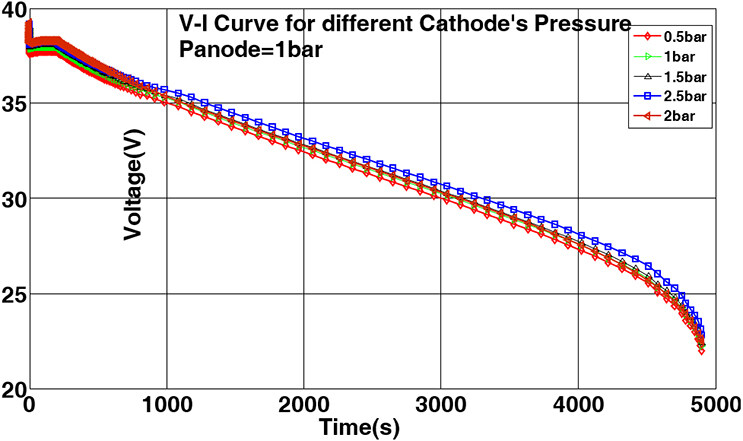
Figure 6. The polarization curve of the model for various cathode pressures.
As shown in Figure 6, an increase in cathode pressure elevates the curves; thus, it can be concluded that the current flow and output voltage of the stack are increased in response to pressure increase on the cathode side. In addition, the voltage drops over time is apparent at all pressures. Considering the polarization curves in Figures 5 and 6, which match to polarization curves of a typical fuel cell, one can conclude that achieving a constant voltage output from the fuel cell without adopting any controlling operations is not practically possible.
5.3 Simulation of the proposed controller and its results
As mentioned above, the controller parameters of the proposed method are designed by utilizing the nonlinear model of a fuel cell in combination with the PSO algorithm [Table 2]. A population of 50 particles and 100 iterations were chosen as the PSO parameters. In addition, Kpand Ki were chosen within the intervals [0,10] and [0,1], respectively. Furthermore, the fixed parameters of PSO were selected as ω = 0.7 and ϕ1 = ϕ2 = 2. The normalized reduction in the PSO cost function with respect to the number of iterations is shown in Figure 7.
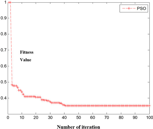
Figure 7. Normalized reduction in the PSO cost function with respect to iterations. PSO: Particle swarm optimization.
Parameters of the proposed controller
| KP1 | KI1 | KP2 | KI2 |
| 1.9884 | 0.01 | 1.9884 | 0.01 |
In the following, the results obtained from the simulation of fuel cell system and PID controller in two modes are presented for comparison, that is using the coefficients either suggested in[23] or resulting from our proposed method.
As shown in Figure 8, the proposed system provides the considered output with a maximum overshoot of 10% and a resting time of 3.5 s. In addition, it is shown that the output voltage with the PID controller has an overshoot of 20% and a risetime of 3.7 s. The variation curves of hydrogen pressure (PH2) and oxygen pressure (PO2) as well as their pressure difference (ΔP) are shown in Figures 9 and 10 for further evaluation.
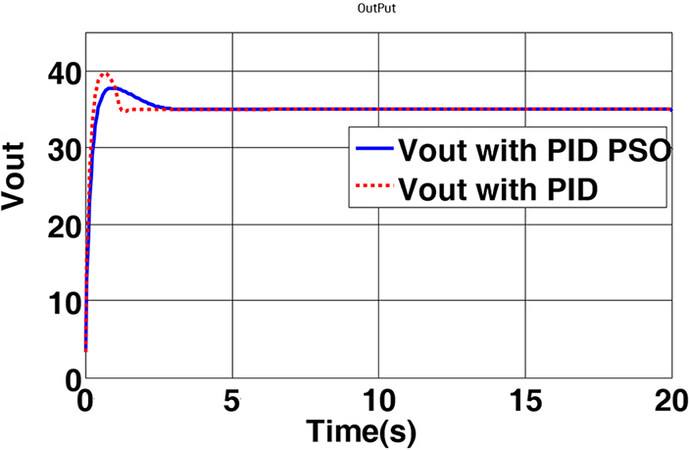
Figure 8. The output voltage of the fuel cell controlled by the proposed method. PID: Proportional-integral-derivative; PSO: particle swarm optimization.
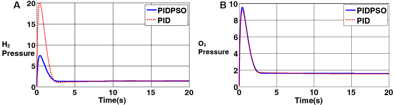
Figure 9. Pressure variation curves for: (A) hydrogen (PH2); and (B) oxygen (PO2). PID: Proportional-integral-derivative; PSO: particle swarm optimization.
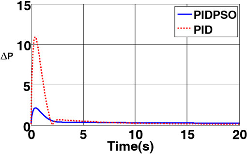
Figure 10. The pressure difference between the two sides of the membrane. PID: Proportional-integral-derivative; PSO: particle swarm optimization.
As shown in Figure 10, the anode side (hydrogen) and cathode side (oxygen) pressures converge to the desired steady state values after a transient period passes. The most significant issue here is the difference between the anode and cathode side pressures, which, if sustained under 2 bars, can save the polymer membrane from severe shocks and increase the stack life. The pressure difference between the two sides is shown in Figure 10.
Figure 10 indicates that the controller designed through the PSO optimization algorithm keeps the pressure difference for all times within an acceptable range, whereas the controller suggested in[28] ignoring the practical parameters exposes the system to pressure differences up to 10 bars. This, in turn, reduces the lifespan of the membrane placed between the cathode and anode.
6. CONCLUSIONS
With the severe nonlinear characteristics of the PEM fuel cell system, using the PID controller for the linear model of the PEM fuel cell system could not guarantee robust control under parametric uncertainty and severe load fluctuations. The use of a linear model-based controller increases the pressure in both anode and cathode areas, which in turn induces a high pressure difference across the polymer membrane, thus reducing the lifespan of the fuel cell. The proposed method uses the PSO algorithm, taking into account practical parameters, to design a PID controller for a nonlinear model of the fuel cell. Comparison of the results obtained from the conventional PID controller and the proposed PID-PSO structure shows that PID-PSO can desirably guarantee the specifications of overshoot, transient time, and settling time for a defined pressure difference across the anode and cathode plates.
In this paper, the nonlinear model of PEM fuel cell system is first extracted with respect to different temperatures and pressures and then evaluated for various temperatures and pressures. In addition, it is shown that the severe nonlinear characteristics complicate controller design for the system. It is illustrated that a PID controller using a linearized model cannot guarantee the performance of the system in practical conditions under uncertainties and severe load changings. Increases up to 20 bars in the anode and cathode side pressures, as well as the very high pressure differences (about 10 bars), reduce the lifespan of the fuel cell.
Finally, as demonstrated in this study, intelligent optimization methods can be sought as one of the most suitable methods for PID controller design directly using a nonlinear system. The PSO algorithm is proposed by taking into account the practical parameters and nonlinearity of the PEM fuel cell model.
In other words, the accomplished design guarantees satisfactory overshoot, transient time, and settling time for a close-to-zero pressure difference between the anode and cathode sides. In addition, because this research would need a test setup with an expensive fuel cell system, it was tested in simulations. In the future, we plan to do research on a real fuel cell system, which will provide valuable results.
DECLARATIONS
Authors’ contributions
Made substantial contributions to design of the PID-PSO is performed and contributed by: Ghasemi J
Performed data acquisition, as well as providing technical notes, technical test on the fuel cell system, and material support is made by: Rakhtala SM, Rasekhi J, Dokhtala SR
Availability of data and materials
Not applicable.
Financial support and sponsorship
None.
Conflicts of interest
All authors declared that there are no conflicts of interest.
Ethical approval and consent to participate
Not applicable.
Consent for publication
Not applicable.
Copyright
© The Author(s) 2022.
REFERENCES
1. Roy AK, Basak P, Biswal GR. Low voltage ride through capability enhancement in a grid-connected wind/fuel cell hybrid system via combined feed-forward and fuzzy logic control. IET Gener Transm Distrib 2019;13:2866-76.
2. Pukrushpan JT, Stefanopoulou AG, Peng H. Control of fuel cell power systems: principles, modeling. Berlin, Germany: Springer Science & Business Media; 2004.
3. Guzzella L. Control of fuel cell power systems: principles, modelling, analysis and feedback design, Jay T. Pukrushpan, Anna G. Stefanopoulou and Huei Peng, Springer, London, UK, xvii+ 161pp. Int J Robust Nonlinear Control 2005;15:553-4.
5. Das V, Padmanaban S, Venkitusamy K, Selvamuthukumaran R, Blaabjerg F, Siano P. Recent advances and challenges of fuel cell based power system architectures and control - a review. Renew Sustain Energy Rev 2017;73:10-8.
6. Grujicic M, Chittajallu K, Pukrushpan J. Control of the transient behaviour of polymer electrolyte membrane fuel cell systems. J Automob Eng 2004;218:1239-50.
7. Priya K, Sathishkumar K, Rajasekar N. A comprehensive review on parameter estimation techniques for Proton Exchange Membrane fuel cell modelling. Renew Sustain Energy Rev 2018;93:121-44.
8. Na WK, Gou B. Feedback-linearization-based nonlinear control for PEM fuel cells. IEEE Trans Energy Convers 2008;23:179-90.
9. Na WK, Gou B, Diong B. Nonlinear control of PEM fuel cells by exact linearization. IEEE Trans Industry Appl 2007;43:1426-33.
10. Matraji I, Laghrouche S, Jemei S, Wack M. Robust control of the PEM fuel cell air-feed system via sub-optimal second order sliding mode. Appl Energy 2013;104:945-57.
11. Chen J, Wu Z, Wu C, Yan C. Observer based fuel delivery control for PEM fuel cells with a segmented anode model. Asian J Control 2019;21:1781-95.
12. Park G, Gajic Z. Sliding mode control of a linearized polymer electrolyte membrane fuel cell model. J Power Sour 2012;212:226-32.
15. Utkin VI. Sliding mode control: mathematical tools, design and applications. Nonlinear and optimal control theory. Berlin, Heidelberg: Springer; 2008. p. 289-347.
16. Savrun MM, İnci M, Büyük M. Design and analysis of a high energy efficient multi-port dc-dc converter interface for fuel cell/battery electric vehicle-to-home (V2H) system. J Energy Storage 2022:45,103755.
17. İnci M. A flexible perturb & observe MPPT method to prevent surplus energy for grid-failure conditions of fuel cells. Int J Hydrogen Energy 2021;46:39483-98.
18. İnci M, Selim Aygen M. A modified energy management scheme to support phase balancing in grid interfaced photovoltaic/fuel cell system. A. in Shams Eng J 2021;12:2809-22.
19. Rakhtala SM. Self-tuning fuzzy logic PID controller with a practical view to PEM fuel cell air supply system. Int J Model, Identif Control 2021;37:187-98.
21. Rakhtala SM, Ghaderi R, Noei AR. Proton exchange membrane fuel cell voltage-tracking using artificial neural networks. J Zhejiang University SCIENCE C 2011;12:338-44.
22. Erdinc O, Vural B, Uzunoglu M. A wavelet-fuzzy logic based energy management strategy for a fuel cell/battery/ultra-capacitor hybrid vehicular power system. J Power Sour 2009;194:369-80.
23. Matraji I, Laghrouche S, Wack M. Pressure control in a PEM fuel cell via second order sliding mode. Int J Hydrogen Energy 2012;37:16104-16.
24. Li Q, Chen W, Wang Y, Jia J, Han M. Nonlinear robust control of proton exchange membrane fuel cell by state feedback exact linearization. J Power Sour 2009;194:338-48.
25. Pukrushpan JT, Peng H, Stefanopoulou AG. Simulation and analysis of transient fuel cell system performance based on a dynamic reactant flow model. ASME Int Mech. Eng Congr Exposit 2002;36290:637-48.
26. Rakhtala SM, Noei AR, Ghaderi R, Usai E. Design of finite-time high-order sliding mode state observer: a practical insight to PEM fuel cell system. J Process Control 2014;24:203-24.
27. Roy AK, Biswal GR, Basak P. An integrated rule-based power management and dynamic feed-forward low voltage ride through scheme for a grid-connected hybrid energy system. J Renew Sustainable Energy 2020;12:056303.
28. Khan M, Iqbal M. Dynamic modeling and simulation of a small wind–fuel cell hybrid energy system. Renew Energy 2005;30:421-39.
29. Zeng W, Zhu W, Hui T, et al. An IMC-PID controller with Particle Swarm Optimization algorithm for MSBR core power control. Nucl Eng Des 2020;360:110513.
30. Iqbal M. Simulation of a small wind fuel cell hybrid energy system. Renew Energy 2003;28:511-22.
Cite This Article
Export citation file: BibTeX | RIS
OAE Style
Ghasemi J, Rakhtala SM, Rasekhi J, Dokhtala SR. PEM fuel cell system to extend the stack life based on a PID-PSO controller design. Complex Eng Syst 2022;2:4. http://dx.doi.org/10.20517/ces.2022.02
AMA Style
Ghasemi J, Rakhtala SM, Rasekhi J, Dokhtala SR. PEM fuel cell system to extend the stack life based on a PID-PSO controller design. Complex Engineering Systems. 2022; 2(1): 4. http://dx.doi.org/10.20517/ces.2022.02
Chicago/Turabian Style
Ghasemi, Jamal, Seyed Mehdi Rakhtala, Jalal Rasekhi, Seyed Reza Dokhtala. 2022. "PEM fuel cell system to extend the stack life based on a PID-PSO controller design" Complex Engineering Systems. 2, no.1: 4. http://dx.doi.org/10.20517/ces.2022.02
ACS Style
Ghasemi, J.; Rakhtala SM.; Rasekhi J.; Dokhtala SR. PEM fuel cell system to extend the stack life based on a PID-PSO controller design. Complex. Eng. Syst. 2022, 2, 4. http://dx.doi.org/10.20517/ces.2022.02
About This Article
Copyright

Data & Comments
Data


 Cite This Article 17 clicks

 Like This Article 31
likes
Like This Article 31
likes


Comments
Comments must be written in English. Spam, offensive content, impersonation, and private information will not be permitted. If any comment is reported and identified as inappropriate content by OAE staff, the comment will be removed without notice. If you have any queries or need any help, please contact us at support@oaepublish.com.