
Integrated control of anti-lock and regenerative braking for in-wheel-motor-driven electric vehicles
 0
0Abstract
The in-wheel motor is increasingly used in electric vehicles due to the significantly improved controllability, response capability, and energy recovery efficiency based on this technology. However, the independent control of in-wheel motors will lead to braking torque distribution problems, especially in a situation where anti-lock braking systems (ABS) are triggered, which may cause the braking energy to be unrecoverable without the coordinated control between anti-lock and RB for two in-wheel motor-driven electric vehicles based on the RB efficiency map. Control-oriented wheel dynamics and slip ratio models of the system are generated. A sliding mode intervention of regenerative braking (RB) control. This paper presents an integrated algorithm to realize the control-based ABS controller is designed to prevent the wheels from locking and to maintain the slip ratio within a desired level, and the stability and robustness of the controller to uncertainties and disturbances are discussed. Moreover, the braking strength of the driver is calculated and divided into different modes to derive a dynamic braking torque distribution to improve the energy recovery efficiency. The hardware-in-the-loop simulation results show that the recovered energy of the proposed strategy under ABS-triggered maneuver is increased by 52.9% than that of the Proportional, Integral, and Derivative controller and can effectively improve the braking performance and stability.
Keywords
1. INTRODUCTION
Many studies imply that almost one-half of the driving energy is dissipated during braking, especially in urban driving circumstances with frequent acceleration and deceleration manipulations[1,2]. The energy consumption during braking processes in different driving cycles is shown in Table 1[3], where UDDS and ECE stand for urban dynamometer driving schedule and Economic Commission of Europe, respectively. Therefore, regenerative braking systems (RBS), which could recapture kinetic energy and greatly reduce power consumption[5], are widely researched in electric or hybrid vehicles[4–6], and brake-by-wire systems[7,8] that support the application of regenerative braking (RB) are investigated as well[7–10]. Xu et al. divided the braking into four different modes for hybrid electric vehicles, and a hierarchical controller is designed to switch the braking mode and to realize optimal efficiency control[11]. Guo et al. presented a piecewise RB strategy for safety and energy-saving control of intelligent electric vehicles[12]. However, the above strategies do not take the vehicle braking stability into consideration, which will cause the vehicle instability in limited conditions. Biao et al. proposed an optimization distribution algorithm-based RB strategy considering vehicle stability during braking situations[13]. The torque distribution ratio is determined by the braking strength and related constraint conditions, and the energy recapture efficiency of the proposed strategy was raised by about fifty percent, but the stability effect of the vehicle was not reflected in the verification part.
Energy consumption during braking processes
| Drive Cycle | UDDS | Japanal015 | ECE |
| UDDS: Urban dynamometer driving schedule; ECE: Economic Commission of Europe. | |||
| Total energy consumption, kJ | 28241 | 1814 | 395 |
| Braking energy consumption, kJ | 13432 | 938 | 207 |
| Rate, % | 47.6 | 51.7 | 52.3 |
The in-wheel motor, which is located directly in the wheels, will significantly enhance controllability and response speed by removing all the intermediate mechanical connections. Additionally, it acquires high efficiency both in motor and generator modes[14]. Therefore, the control strategies for in-wheel motor-driven electric vehicles (IWMDEV) have been widely studied. Karabacak et al. designed a fuzzy logic controller in the motor mode and a pulse width modulation controller in the RB mode for two IWMDEV (2IWMDEV), and the algorithm is embedded in a DSP microcontroller[15]. Gang and Zhi proposed an RB control method for four IWMDEV (4IWMDEV) under urban scenes using motor efficiency maps, and the simulation results validated the effectiveness of the proposed method under urban driving cycles[16]. A feedback hierarchical controller for 4IWMDEV is presented by Chen et al. to control the vehicle to track the desired velocity and assign braking torque to increase energy recovery[17]. However, in addition to improving recovery efficiency, the braking performance and stability should also be considered, especially under heavy braking strength request conditions, which will cause the braking torque distribution problem[18–21].
Dadashnialehi et al. estimated wheel speed accurately based on the back electromotive force of the brushless DC (BLDC) motor, and proposed a sensorless anti-lock braking system (ABS) for IWMDEVs both theoretically and experimentally[22]. Wang and He presented an improved linear quadratic Gaussian controller to derive braking torques for ABS control, and a varying charge voltage in steps control is designed to recover more energy[23]. Yang et al. employed a combination method of logic threshold and phase plane theory to generate the braking torque for ABS control and then proposed a coordination strategy of RBS and ABS to increase recovery efficiency for ABS-triggered scenarios[24]. Although these methods integrate the RBS and ABS control together to improve the braking performance and recover more energy, rarely do these methods address the stability problem during braking situations. He et al. took the braking stability into consideration and designed a combined sliding mode controller to realize ABS control[25]. Tang et al. presented a comprehensive controller: the braking torque distribution strategy. This strategy considers safety and recovery efficiency optimization while also involving a coordinated strategy of RBS and ABS based on model predictive control[26]. Pei et al. proposed a coordinated controller to realize optimal energy regeneration and braking stability for distributed electric vehicles by regulating hydraulic and RB torques[27]. However, the braking intension is rarely considered during the coordinated control of energy recovery and braking stability.
The above studies indicate that the problem of how to simultaneously improve the braking stability and regeneration efficiency for 2IWMDEVs considering braking intension is still not resolved. This paper aims to present an integrated control method to combine ABS and RBS control, even in emergency braking situations, and synthetically improve braking performance, recovery efficiency, stability, and road adaptability of 2IWMDEVs. The main contributions of the paper include a robust SMC-based ABS controller to make full use of the road conditions under different adhesion coefficients and an RBS strategy to distribute the regenerative and hydraulic braking torques to recapture more energy.
The rest of the paper is organized as follows: In the second section, a SMC-based ABS controller is proposed for 2IWMDEVs, including wheel dynamics models, slip ratio models, ABS controllers, and stability and robustness analysis of the controller. The distribution method of regenerative and frictional braking torques is designed in the third section. In the fourth section, the RB efficiency map is generated through bench experiments. Hardware-in-the-loop (HIL) simulations are conducted in the fifth section to validate the proposed algorithm. Finally, within the same section, conclusions are made, and a future work outlook is provided.
2. SMC-BASED ABS CONTROLLER
2.1. Wheel dynamics
An electric vehicle equipped with two front in-wheel motors and RBSs is applied in the paper, and the two rear wheels are driven by a traction motor. Figure 1 shows rotational dynamics of single wheels, where

Figure 1. Wheel dynamic.
The following assumptions are made.
● The tire rolling resistance and vehicle aerodynamics are negligible during braking processes.
● Tire self-aligning torque is negligible.
● The chamber angle of each wheel is zero.
The dynamic equations are as follows.
where
Combining Equations (1), (2), and (3) yields
where the slip ratio could be expressed as follows during braking situations
Taking the derivative of Equation (5) with respect to time and substituting Equation (4) into it, we have
Figure 2 represents experimental results based on JAC iEV7S, a four-wheel double-drive electric vehicle; it shows the relationship between slip ratios and longitudinal utilized friction coefficients, and the curve could be simplified with two lines intersecting at the peak utilized friction coefficient point. The longitudinal utilized friction coefficient can be described as follows

Figure 2. The curve of
where
Substituting Equation (7) into Equation (6), after some manipulations, we have
2.2. ABS controller
ABS controllers are designed to maintain the slip ratios of wheels at a particular level, where both the longitudinal and lateral adhesion forces reach their maximum value. To this end, we define the sliding surface in terms of slip ratio tracking errors as
It is apparent that if we find a control law to make
where
Differentiating Equation (9) with respect to time and combining Equation (8) yield
Since
2.3. Stability analysis of the ABS controller
The Lyapunov function is designed as follows:
Thus,
Substituting Equation (8) into Equation (15), after some manipulations, we have
Substituting Equation (13) into Equation (16) yields
The stability of the proposed ABS controller has been proved, and the system will move to the surface according to Equation (17). Assume that the initial slip ratio tracking error is finite, and then,
2.4. Robustness analysis of the ABS controller
Nonlinear characteristics, disturbances, and uncertainties always exist in practice control systems, e.g., motor torques, estimated vehicle velocity, and sensor noise. Therefore, if the controller is to be applied in practice, it is essential to analyze its robustness.
2.4.1. Disturbance analysis of motor torque
In the actual motor control process, it is generally difficult to achieve real-time precise implementation of the desired motor torque listed in Equation (13), and the torque tracking error may reduce the control performance or even cause the controller instability. Moreover, the additive disturbance will affect the design value of convergence factor
Replacing
Note that the first derivative of the Lyapunov function should be negative definite to ensure the system stability; the torque disturbance should satisfy the following inequality constraints.
The above equation means that the factor of convergence
2.4.2. Disturbance analysis of vehicle velocity
The actual vehicle velocity is normally obtained from the transmission output shaft speed sensor or estimated based on the wheel speed sensor. However, the above methods will cause velocity error, which leads to slip ratio error
For the controller, the actual slip ratio is expressed as
From the above equation,
2.4.3. Disturbance analysis of sensor noise
Sensor noise has a significant influence on the stability of a closed-loop system, and the signal fluctuation will degrade measurement accuracy and affect state parameter calculation; e.g., the fluctuation of wheel velocity signals will influence the slip ratio calculation according to Equation (5). High-frequency filters[7] are adopted to estimate the actual value, decrease measurement noise, and guarantee the system stability.
3. DISTRIBUTION OF REGENERATIVE AND FRICTIONAL BRAKING TORQUES
With two front in-wheel motors, the regenerative and frictional blending brake is related, and the optimal objective is to improve energy recovery efficiency and braking stability. To this end, the distribution of the regenerative and frictional braking torques should be first discussed. As shown in Figure 3, the requested braking pressure of the driver is calculated according to brake pedal stroke and the characteristics of brake pressure

Figure 3. Braking torque control schematic.
To improve tire-road friction coefficient (TRFC) utilization efficiency and directional stability during braking situations, both the front and rear wheels should be locked simultaneously, and the desired braking forces of the front and rear axles are expressed as follows
where
With manipulations of Equation (23), we have
As shown in Figure 3, the braking strength z is achieved according to the requested braking force and
(A) When
where
(B) When
where
(C) When
where
4. EFFICIENCY MAP OF THE RB SYSTEM
An optimal energy recovery method should be designed based on an efficiency map by minimizing the transfer loss during blending brake, and the motor-to-battery efficiency is calculated by the following expression.
where
Figure 4 shows the test bench; a motor with the same characteristics is used instead of the in-wheel one, and a magnetic powder brake is adopted to simulate the vehicle rolling resistance to prevent the motor from moving or to supply kinetic energy during braking. Batteries and sensors are installed to collect energy recapture information. With Equation (28), the RB efficiency map is generated from bench tests under different braking torques and wheel velocities and is fitted, as shown in Figure 5, based on the experimental data.
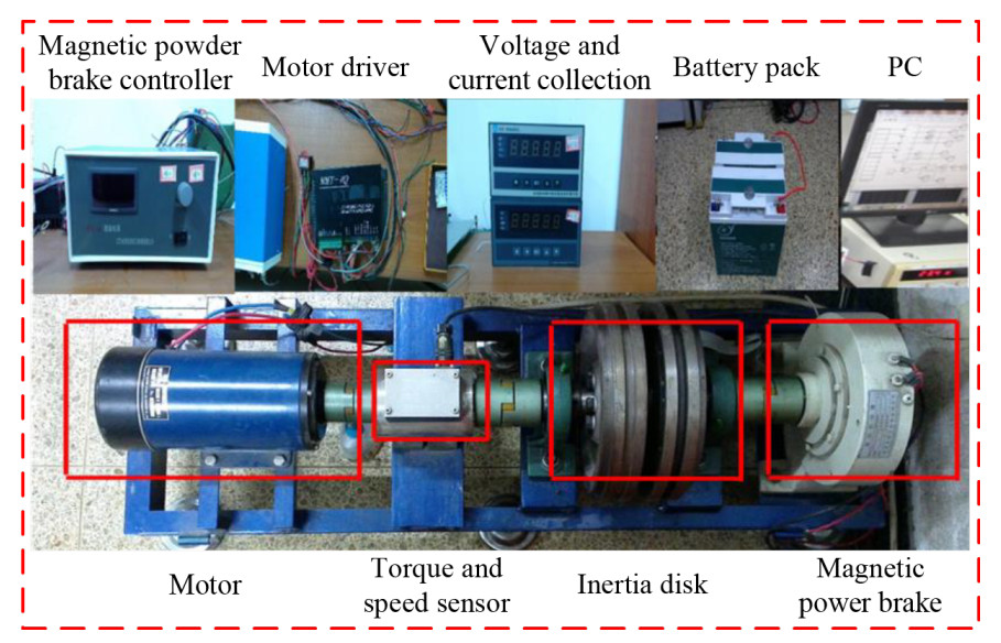
Figure 4. Test bench.
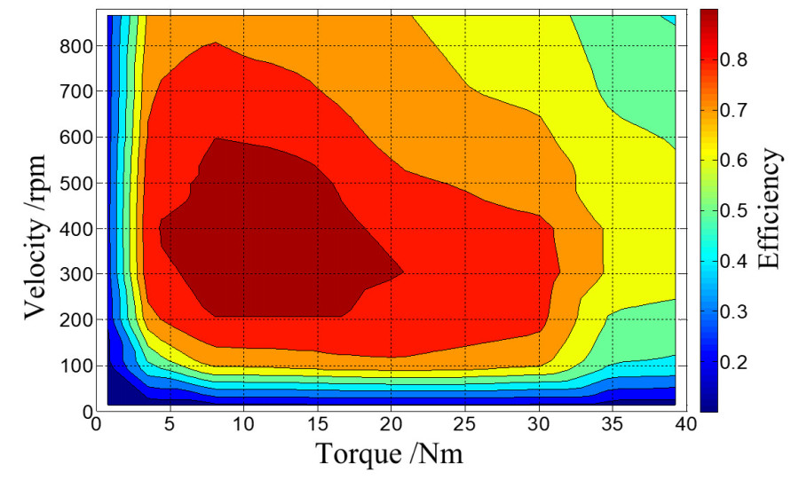
Figure 5. RB efficiency map.
5. HIL SIMULATION AND RESULTS ANALYSIS
A HIL simulation system equipped with vehicle-manipulator systems, steering systems, and hydraulic braking system is developed to evaluate the performance of the proposed integrated algorithm. Figure 6 displays the system composition. Figure 7 illustrates the algorithm block diagram. In this diagram, the steering angle and braking torque are requested by the driver. The vehicle model is then simulated using the CarSim software. The torque distribution and ABS algorithm code are generated using MATLAB/Simulink and downloaded to the dSPACE/SCALEXIO for execution. Finally, the recaptured energy is stored in the battery pack.The vehicle model and controller parameters are listed in Table 2.
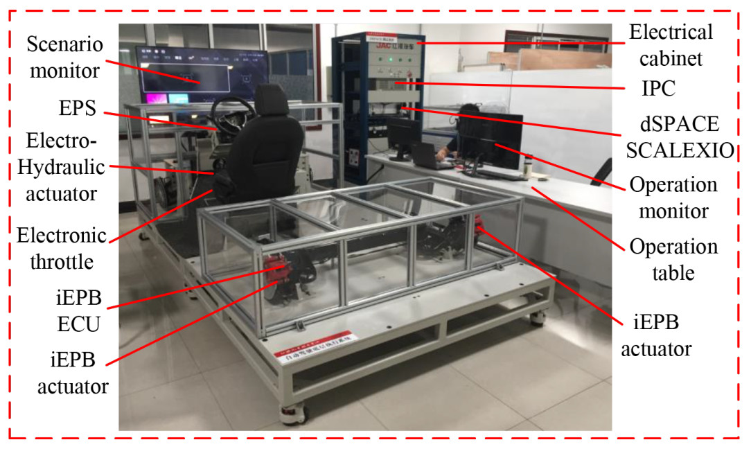
Figure 6. HIL simulation system.
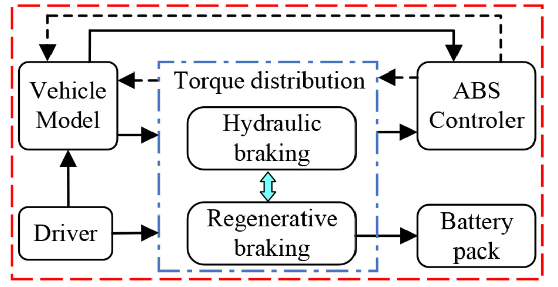
Figure 7. Algorithm block diagram.
Vehicle model and controller parameters
| Parameters | Value |
| Vehicle mass ( | 1,855 kg |
| Rotational inertia of the front/rear tire ( | 1.5 kg |
| Effective wheel rolling radius ( | 316 mm |
| Height of the center of gravity ( | 530 mm |
| Distance between the front and rear axles ( | 2,490 mm |
| Front axle to the center of gravity ( | 1,100 mm |
| Rear axle to the center of gravity ( | 1,390 mm |
| Effective radius of the front brake disc ( | 105 mm |
| Piston radius of the front wheel cylinder ( | 27 mm |
| Friction coefficient of the front brake pad ( | 0.4 |
| Maximum RB torque ( | 1,200 N |
| Convergence factor ( | 0.02 |
| Boundary layer thickness ( | 0.1 |
5.1. Results on homogeneous surface
A steering-braking maneuver with a 75 km/h initial forward velocity is performed on a high-mu homogeneous surface to verify the proposed algorithm, and a Proportional, Integral, and Derivative (PID) controller is also simulated to compare with the proposed one. Figure 8 shows the time histories of vehicle and wheel velocities derived from the two controllers under the specified simulation maneuver. At the end of the simulation, the four wheels of the PID controller are locked, while those of the SMC controller are not during the whole simulation, which indicates that the proposed SMC controller achieves better anti-lock performance than the PID controller. As shown in Figure 8A and B, compared with PID controllers, the regulation frequency of the front wheels of SMC controllers is lower, which will improve the vehicle stability and comfort.
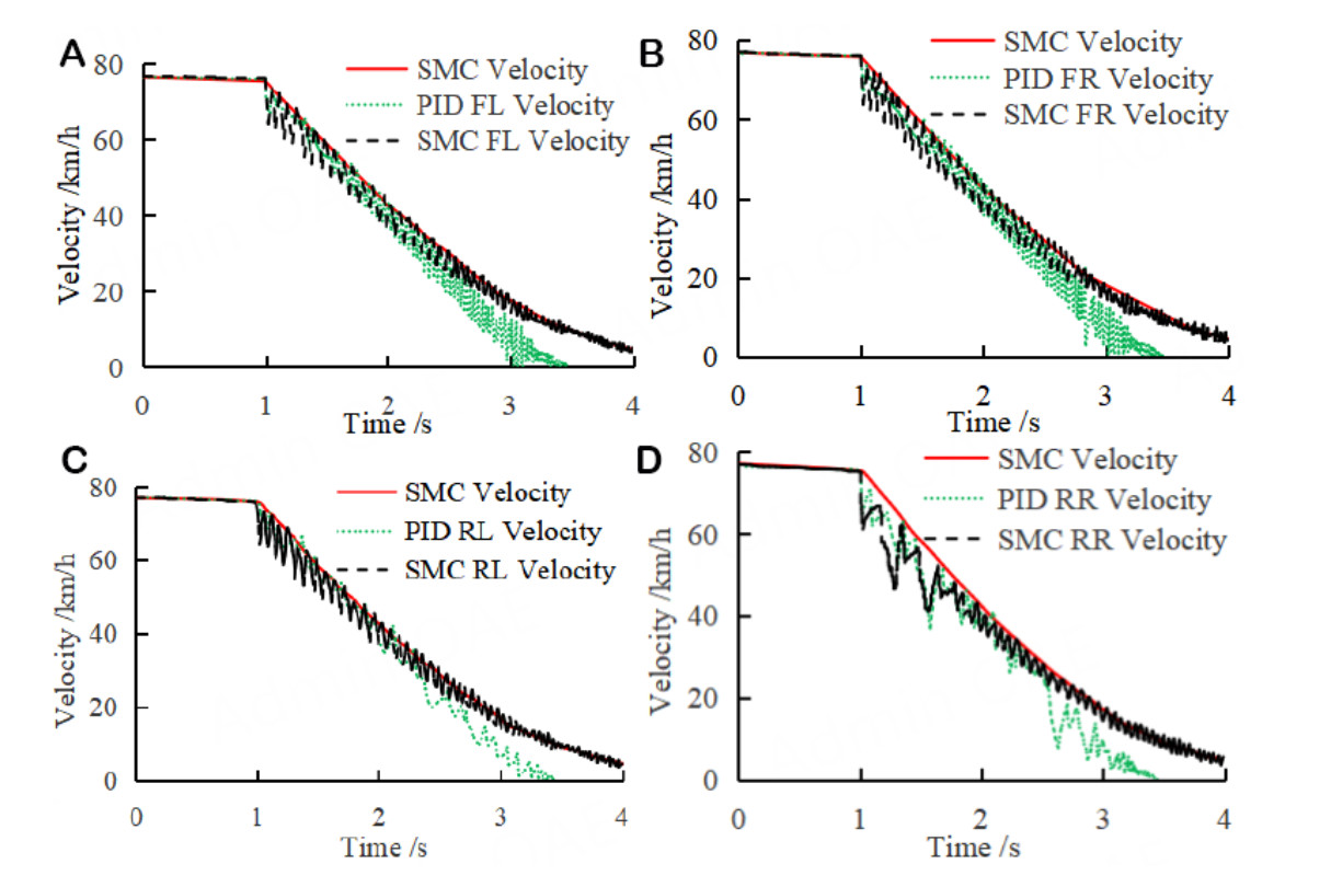
Figure 8. Velocities of vehicles and wheels. (A) Front left wheel; (B) Front right wheel; (C) Rear left wheel; (D) Rear right wheel.
Figure 9 depicts the comparison of wheel slip ratios derived from the two controllers. Slip ratios of all the wheels of both the controllers are within a reasonable range near the optimal value in the beginning, and then, the fluctuation of the PID controller dramatically rises to approximately one while that of the SMC controller is still reasonable. The high braking torque regulation frequency of front wheels leads to frequent and dramatic chattering of the slip ratio. The results illustrate that the SMC controller acquires a significantly better tracking performance of the optimal slip ratio.

Figure 9. Slip ratio of the wheels.(A) Front left wheel; (B) Front right wheel; (C) Rear left wheel; (D) Rear right wheel.
Figure 10 presents the time histories of sideslip angular velocities and yaw rates. In Figure 10A, although the fluctuations of both two controllers are large in the beginning because of the steering input, the sideslip angular velocity derived from the SMC controller is constrained within a very small boundary in the remaining simulation process, while that of the PID method is still variate intensive. As shown in Figure 10B, the magnitude of the yaw rate of the PID controller is much larger than that of the SMC controller, especially at the end of the simulation. The results indicate that the proposed method achieves a better handling and stability performance than that of the PID controller.
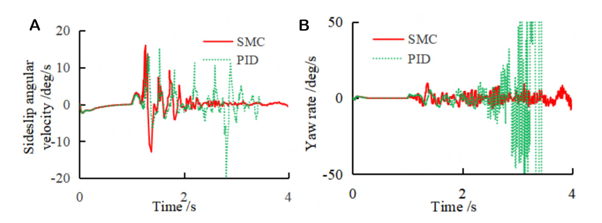
Figure 10. Vehicle sideslip angular velocity and yaw rate. (A) Sideslip angular velocity; (B) Yaw rate.
Figure 11 and Figure 12 reveal the comparison of energy recovery between the SMC and PID controllers. Since the braking torque generated by the SMC controller is much bigger than that of the PID controller before about 1.5 s, the recapture energy of the SMC controller is larger during the beginning period. After about 2.4 s, the braking torque derived from PID is larger than SMC, which causes a greater wheel velocity variation even to lock, as shown in Figure 8. However, the recaptured energy by SMC grows faster than by PID due to the distribution of braking torques, and the main growth of recovery energy by SMC lies in this period. Overall, the SMC-based energy recovery efficiency is significantly higher than that of PID-based, and the efficiency increases by 52.9%.
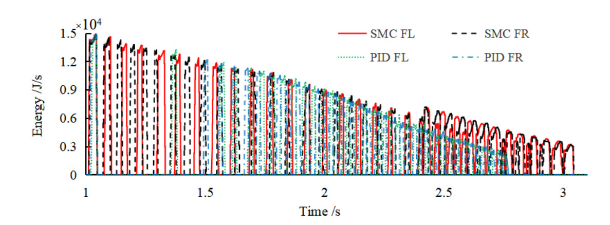
Figure 11. Distribution of the regenerative braking energy.

Figure 12. Comparison of total recaptured energy.
5.2. Results on the split surface
A driver-in-the-loop simulation on the split surface with a 70 km/h initial forward velocity is conducted to evaluate the effectiveness of the proposed algorithm in non-ideal scenarios, and the TRFCs of the left and right sides are 0.3 and 0.8, respectively. Figure 13A shows the master cylinder pressure applied by the driver and the wheel cylinder pressures generated by the ABS controller. The applied pressure (about 8 MPa) is too big to anti-lock the wheels, and the ABS is triggered to regulate the wheel pressures. Furthermore, the generated pressures of the left wheels change more frequently than the right wheels due to the lower TRFC, and the pressure increasement times of the front left (FL) and rear left (RL) wheels are 25 and 26 in approximately eight seconds, whereas that of the front right (FR) and rear right (RR) are two and 24 times, respectively. Although the left wheels are easier to lock up due to their huge fluctuations of slip ratios, the frequent regulation of braking pressures keeps the wheels in anti-lock status, as shown in Figure 13B. The maximum equivalent braking pressure generated by the RB motor is calculated by the following expression.
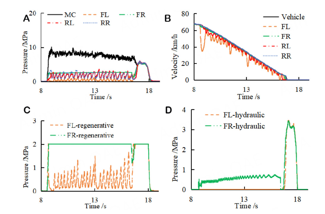
Figure 13. Simulation results on the split surface. (A) Braking pressure; (B) Velocities; (C) Regenerative braking; (D) Hydraulic braking.
With the parameter values listed in Table 2, the value of
6. CONCLUSIONS AND FUTURE WORK
An integrated algorithm is proposed for ABS and RBS coordinated control of 2IWMDEVs to improve vehicle braking stability and energy recovery efficiency, including both RB control on the front two wheels and anti-lock braking control on all four wheels. HIL simulations are carried out to verify the effectiveness of the integrated algorithm, and the results show that the ABS controller can prevent wheels from being locked to ensure braking performance and vehicle stability. With the distribution strategy of braking torques among in-wheel motors and friction brakes considering the required braking torque and strength, the recovered energy of the proposed strategy under ABS-triggered maneuver is increased by 52.9% than that of the PID controller. Therefore, the presented integrated algorithm can not only maintain the slip ratio within the desired range and braking stability but also achieve excellent energy recapture efficiency, which is significant to ensure safety and economy of the 2IWMDEVs.
Our future work will concentrate on adaptive threshold value design for braking modes division, experimental validation of the proposed algorithm through in-vehicle field and road tests with the consideration of uncertainties, and modification of the proposed algorithm to adapt to 4IWMDEVs.
DECLARATIONS
Acknowledgments
The authors would like to thank the anonymous reviewers for their valuable comments.
Authors' contributions
Made substantial contributions to the conception and design of the study and performed data analysis and interpretation: Yong J, Dong Y, Zhang Z
Performed data acquisition and provided administrative, technical, and material support: Zhang Z, Feng N, Li W
Availability of data and materials
Not applicable.
Financial support and sponsorship
This work was supported by the National Natural Science Foundation of China (No. 52002009), Beijing Natural Science Foundation (No. 3222003), and the State Key Laboratory of Automotive Safety and Energy under Project No. KF2010.
Conflicts of interest
All authors declared that there are no conflicts of interest.
Ethical approval and consent to participate
Not applicable.
Consent for publication
All the authors have agreed to publish the paper.
Copyright
© The Author(s) 2024.
REFERENCES
1. Feng N, Yong J, Zhan Z. A direct multiple shooting method to improve vehicle handling and stability for four hub-wheel-drive electric vehicle during regenerative braking. J Automot Eng 2019;234:1047-56.
2. Zhao W, Wu G, Wang C, Yu L, Li Y. Energy transfer and utilization efficiency of regenerative braking with hybrid energy storage system. J Power Sources 2019;427:174-83.
3. Bravo RRS, De Negri VJ, Oliveira AAM. Design and analysis of a parallel hydraulic-pneumatic regenerative braking system for heavy-duty hybrid vehicles. Appl Energy 2018;225:60-7.
4. Xu M, Peng J, Ren X, Yang X, Hu Y. Research on braking energy regeneration for hybrid electric vehicles. Machines 2023;11:347.
5. Choo KM, Won CY. Design and analysis of electrical braking torque limit trajectory for regenerative braking in electric vehicles with PMSM drive systems. IEEE Trans Power Electron 2020;35:13308.
7. Yong J, Gao F, Ding N, He Y. Design and validation of an electro-hydraulic brake system using hardware-in-the-loop real-time simulation. Int J Automot Technol 2017;18:603-12.
8. Han W, Xiong L, Yu Z. A novel pressure control strategy of an electro-hydraulic brake system via fusion of control signals. J Automot Eng 2019;233:3342-57.
9. Chen Q, Lv Z, Tong H, Xiong Z. Clamping force control strategy of electro-mechanical brake system using VUF-PID controller. Actuators 2023;12:272.
10. Wang Z, Ding X, Zhang L. Chassis coordinated control for full X-by-wire four-wheel-independent-drive electric vehicles. IEEE Trans Veh Technol 2023;72:4394-410.
11. Xu Q, Wang F, Zhang X, Cui S. Research on the efficiency optimization control of the regenerative braking system of hybrid electrical vehicle based on electrical variable transmission. IEEE Access 2019;7:116823-34.
12. Guo J, Li W, Wang J, Luo Y, Li K. Safe and energy-efficient car-following control strategy for intelligent electric vehicles considering regenerative braking. IEEE Trans Intell Transport Syst 2022;23:7070-81.
13. Biao J, Xiangwen Z, Yangxiong W, Wenchao H. Regenerative braking control strategy of electric vehicles based on braking stability requirements. Int J Automot Technol 2021;22:465-73.
14. Hosseini Salari A, Mirzaeinejad H, Fooladi Mahani M. A new control algorithm of regenerative braking management for energy efficiency and safety enhancement of electric vehicles. Energy Convers Manag 2023;276:116564.
15. Karabacak Y, Uysal A. An embedded controller application with regenerative braking for the electric vehicle. Elektron ElektroTech 2020;26:10-17.
16. Gang L, Zhi Y. Energy saving control based on motor efficiency map for electric vehicles with four-wheel independently driven in-wheel motors. Adv Mech Eng 2018;10:1-18.
17. Chen J, Yu J, Zhang K, Ma Y. Control of regenerative braking systems for four-wheel-independently-actuated electric vehicles. Mechatronics 2018;50:394-401.
18. Lupberger S, Degel W, Odenthal D, Bajcinca N. Nonlinear control design for regenerative and hybrid antilock braking in electric vehicles. IEEE Trans Contr Syst Technol 2022;30:1375-89.
19. Ma Z, Sun D. Energy recovery strategy based on ideal braking force distribution for regenerative braking system of a four-wheel drive electric vehicle. IEEE Access 2020;8:136234-42.
20. Zhang Z, Ma R, Wang L, Zhang J. Novel PMSM control for anti-lock braking considering transmission properties of the electric vehicle. IEEE Trans Veh Technol 2018;67:10378-86.
21. Chen Y, Chen S, Zhao Y, Gao Z, Li C. Optimized handling stability control strategy for a four in-wheel motor independent-drive electric vehicle. IEEE Access 2019;7:17017-32.
22. Dadashnialehi A, Bab-hadiashar A, Cao Z, Kapoor A. Intelligent sensorless antilock braking system for brushless in-wheel electric vehicles. IEEE Trans Ind Electron 2015;62:1629-38.
23. Wang J, He R. Varying charge voltage in the steps control method of ABS for in-wheel motors driven electric vehicles based on an improved LQG scheme. IEEE Access 2018;6:15039-50.
24. Yang Y, Tang Q, Bolin L, Fu C. Dynamic coordinated control of regenerative braking system and anti-lock braking system for electrified vehicles under emergency braking conditions. IEEE Access 2020;8:172664-77.
25. He L, Ye W, He Z, Song K, Shi Q. A combining sliding mode control approach for electric motor anti-lock braking system of battery electric vehicle. Control Eng Pract 2020;102:104520.
26. Tang Q, Yang Y, Luo C, Yang Z, Fu C. A novel electro-hydraulic compound braking system coordinated control strategy for a four-wheel-drive pure electric driven by dual motors. Energy 2022;241:122750.
27. Pei X, Pan H, Chen Z, Guo X, Yang B. Coordinated control strategy of electro-hydraulic braking for energy regeneration. Control Eng Pract 2020;96:10434.
Cite This Article
Export citation file: BibTeX | RIS
OAE Style
Yong J, Dong Y, Zhang Z, Feng N, Li W. Integrated control of anti-lock and regenerative braking for in-wheel-motor-driven electric vehicles. Complex Eng Syst 2024;4:2. http://dx.doi.org/10.20517/ces.2023.36
AMA Style
Yong J, Dong Y, Zhang Z, Feng N, Li W. Integrated control of anti-lock and regenerative braking for in-wheel-motor-driven electric vehicles. Complex Engineering Systems. 2024; 4(1): 2. http://dx.doi.org/10.20517/ces.2023.36
Chicago/Turabian Style
Yong, Jiawang, Yiyao Dong, Zhilin Zhang, Nenglian Feng, Wanting Li. 2024. "Integrated control of anti-lock and regenerative braking for in-wheel-motor-driven electric vehicles" Complex Engineering Systems. 4, no.1: 2. http://dx.doi.org/10.20517/ces.2023.36
ACS Style
Yong, J.; Dong Y.; Zhang Z.; Feng N.; Li W. Integrated control of anti-lock and regenerative braking for in-wheel-motor-driven electric vehicles. Complex. Eng. Syst. 2024, 4, 2. http://dx.doi.org/10.20517/ces.2023.36
About This Article
Special Issue
Copyright

Data & Comments
Data
0

 Cite This Article 6 clicks

 Like This Article 13
likes
Like This Article 13
likes


Comments
Comments must be written in English. Spam, offensive content, impersonation, and private information will not be permitted. If any comment is reported and identified as inappropriate content by OAE staff, the comment will be removed without notice. If you have any queries or need any help, please contact us at support@oaepublish.com.